So far, we have considered five ideas in linear state-space control:
acker program.
As you have no doubt discovered, it can be very difficult to design a controller by first selecting candidate poles, and then using a program like acker to determine the associated gains.
The problem is that natural frequencies can have a complicated impact on trade-offs we care about, such as minimizing response time without exceeding equipment limits. In the next section, we are going to develop a different approach to determining the feedback gains, referred to as linear-quadratic regulation (LQR). But before we describe that approach, we are going to consider a thermal regulation problem, just to convince ourselves that we need something better than design by pole-placement.
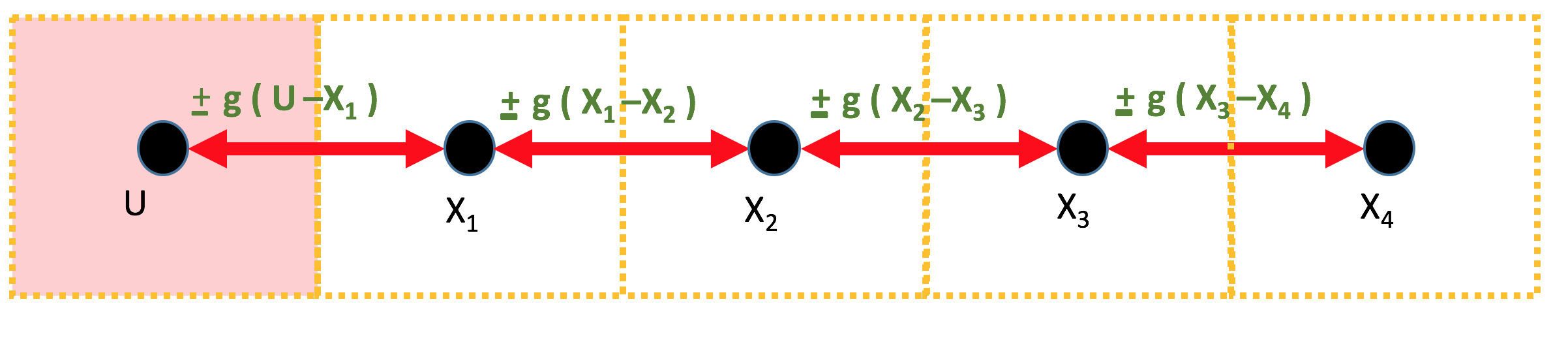
Suppose you are designing the controller for a five-compartment heating
system, as shown in the figure below. The pink compartment in the figure is the
Having encapsulated the physical details in \( g\), the equations for the temperature change in one sample period, \( T \) are not complicated. The change is equal to the product of the period length and the difference between the "flow" in from the left, and the "flow" out to the right. That is, \begin{eqnarray} x_1[n] &=& x_1[n-1] + T \left( g \cdot (u[n-1] - x_1[n-1])- g\cdot(x_1[n-1]-x_2[n-1]) \right) \\ x_2[n] &=& x_2[n-1] + T \left( g \cdot (x_1[n-1] - x_2[n-1])-g\cdot(x_2[n-1]-x_3[n-1]) \right) \\ x_3[n] &=& x_3[n-1] + T \left( g \cdot (x_2[n-1] - x_3[n-1])-g\cdot(x_3[n-1]-x_4[n-1]) \right) \\ x_4[n] &=& x_4[n-1] + T \left( g \cdot (x_3[n-1] - x_4[n-1]) \right), \end{eqnarray} where \( T \) is the sample period in minutes, and \( x_i \) is the temperature of the \(i^{th}\) compartment in centigrade degrees. For those more familiar with other temperature scales, recall that for centigrade, zero is the freezing point of water, \( 20 \) is a comfortable room temperature, and \( 100 \) is the water boiling point.
For this heating system, the control problem is to adjust the heater's temperature so that all four compartments achieve a desired temperature as quickly as possible, and then adjust the heater to maintain that temperature. But, this physical system has constraints. Allowing the heater to get too hot, even briefly, is dangerous. Very high heater tenperatures could start a fire, or increase the frequency and severity of accidental burns. In addition, allowing compartment temperatures to exceed the target by more than a few degrees, even temporarily, may be problematic (particularly if the compartments are occupied).
The heating system constraints should not be dismissed as a problem-specific nuisance. Every real system has physical constraints, and addressing them is a central part of control system design. If fact, we started this section with a very specific physical example, rather than equations and derivations (but those are coming too), because the constraints are easily lost in the mathematics, as is the motivation for finding a design approach other than placing natural frequencies.
We can formulate the temperature control problem as a single-input, single-output \(A,B,C,D\) state-space system,
\begin{eqnarray} \textbf{x}[n] &=& \textbf{A}\textbf{x}[n-1] + \textbf{B}u[n-1] \\ y[n] &=& \textbf{C}\textbf{x}[n] + Du[n], \end{eqnarray}where \( \textbf{x} = [x_1,x_2,x_3,x_4]^T \), \( u \) is the heater temperature, and the \(A,B,C,D \) matrices can be found in the python script thermal_example.py.
In the python program, there is a line near the top,
nat_freqs = np.array([0.5,0.5,0.5,0.5])
which sets the desired natural frequencies for the feedback system. These
natural frequencies are used by acker to determine the feedback gains,
\[
\textbf{K} = [k_1, k_2, k_3, k_4].
\]
If you try running the python program as is, you should see something like the figure below. And if you examine the simulated compartment and heater temperatures, you should notice several important characteristics. First, the controller is fast, the compartments settle to room temperature in less than 15 minutes. But, you should also be alarmed by how that speed was achieved. The maximum temperatures are thousands of degrees, and the heater has to get hotter than the surface of the sun!!. And it may seem a little anti-climactic, but notice that temperature of the heater also has to go negative, and refridgerate the compartments.
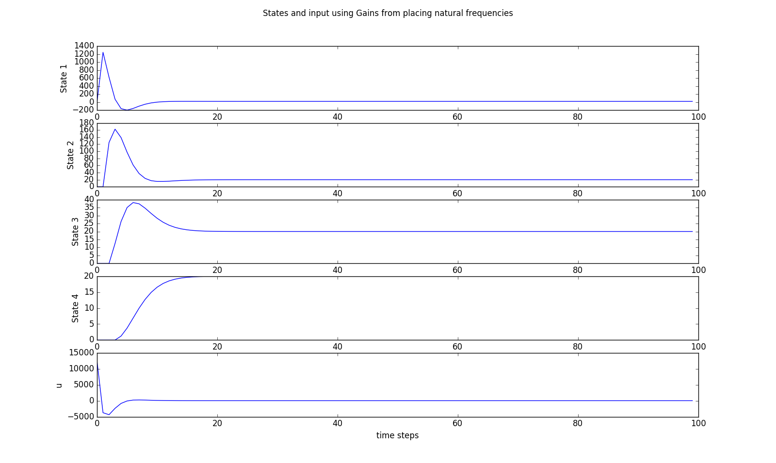
Clearly setting all the natural frequencies to \( 0.5 \) was too aggressive,
but what should we do? Should we set all the natural frequencies to the
same value, or should we chose several different values? And what values? In the next question, we will
ask you to find natural frequency values so that acker produces gains
that give you controller performance that matches ours. The question is not graded,
try it three times by editing the python file thermal_example.py , then
look at our results and verify them in your code.
For this problem, you will be determining the gains for a better controller for the four-compartment heating system, by using the natural frequency placement approach (more commonly referred to as pole-placement). Please answer the questions below by modifying the natural frequencies in the python code in the file thermal_example.py. The code will do most of the mechanical work for you, and plot the simulation results for your designs.
You will be trying to pick natural frequencies that lead to a controller that minimizes the time for the compartments to settle to their final temperatures, while satisfying constraints associated with the physical system. The two constraints your solutions should always meet are:
Modify the natural frequency placement in the thermal_example.py file to set all the natural frequencies to 0.99. That is, change
nat_freqs = np.array([0.5,0.5,0.5,0.5])
to
nat_freqs = np.array([0.99,0.99,0.99,0.99])
With all \( 0.99 \) natural frequencies, how many minutes does it take for all the compartment temperatures to be within one degree of their target temperature?
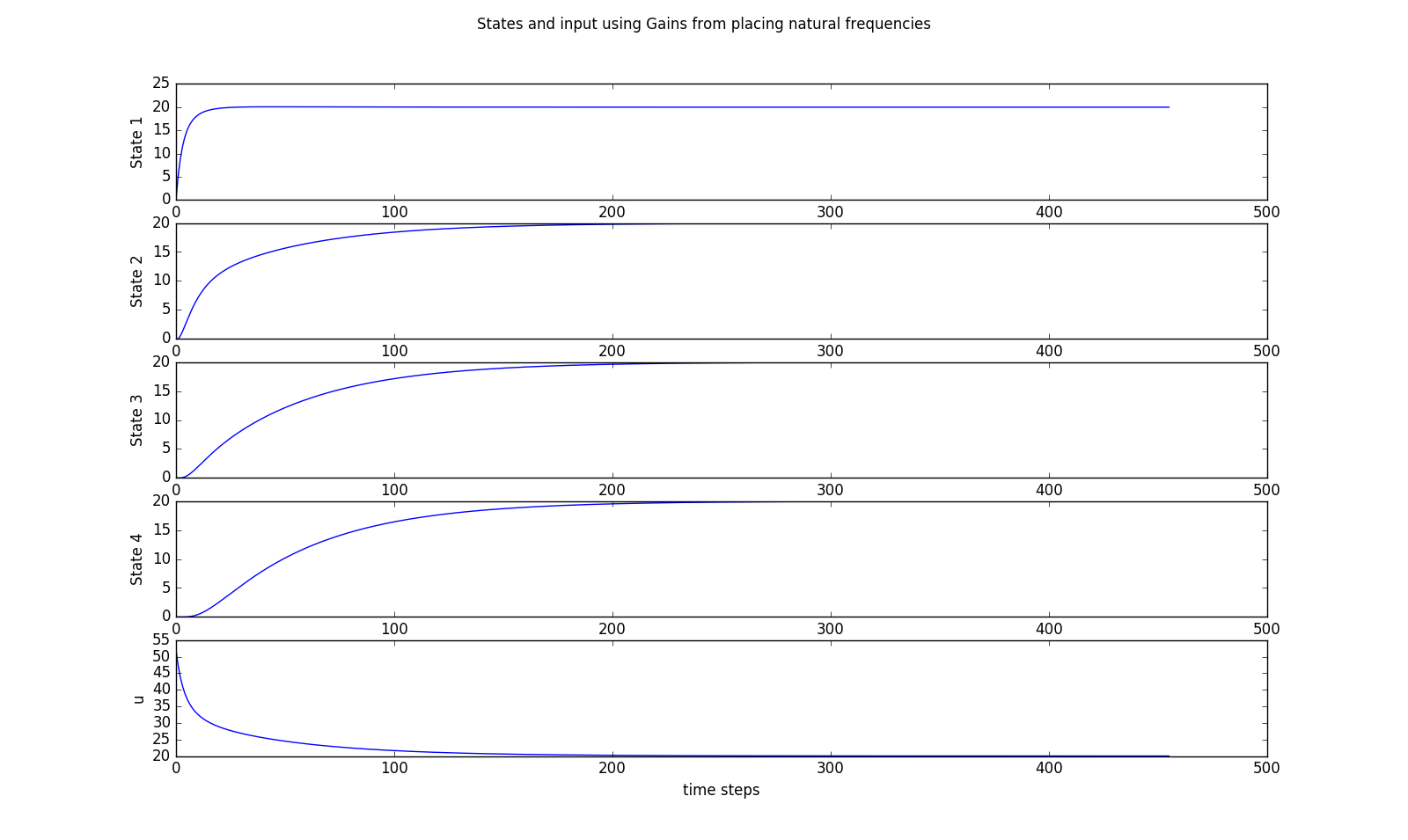
Can you find a set of natural frequencies that performs better than the results shown below (satisfies the constraints and settles to within one degree in less than \( 165 \)minutes)? Please order the natural frequencies from smallest to largest. Note that this problem is ungraded, and is intended to demonstrate that it can be very difficult to determine how to place natural frequencies so as to optimize common performance metrics.
nat_freqs = np.array([0.63,0.73,0.87,0.98]);
Determine OUR answer for the natural frequencies in the previous problem, and then use the python code to determine the associated gains For our set of natural frequencies. What were the related set of gains? Please note, this question is intended to help you verify that you understand the python program.
\( K = [0.9, 0.35, 0.2, 0.15] \)
Did you find natural frequencies for the heating system problem that were better than ours?
Consider the wind turbine generator, like the one in the figure below, with fins that help it automatically align to incoming wind direction. Imagine adding a speed-adjustable rotor beneath the turbine, and then controlling the rotor speed to improve the alignment between the turbine and the optimal wind direction. A good feedback controller should align the turbine faster, and minimize the extent and duration of misalignment due to cross-wind gusts.

To design a state-feedback controller for the rotor-turbine system, we first need a state-space model. And the simpliest such model would be a first-order LDE, \[ x[n] = a x[n-1] + b u[n-1]. \] where \( x \) is the misalignment angle, or more specifically, the angle between the turbine and the dominate wind direction; \( a \) is the one-period misalignment reduction factor (due to the fins), \( u \) is the rotational speed of the rod rotor, and \( b = T\) is the sample period. If the fins always realign the turbine after a cross-wind gust, even without feedback (\( u = 0 \)), then the \( a \) in our model must have a magnitude less than one, \( |a| < 1\).
One particularly effective approach to analyzing the system's performance is to model a misalignment produced by a wind gust as a non-zero initial condition, \( x[0] \), equal to the misalignment immediately after the gust, we can solve the LDE and determine an explicit formula for \(x[n]\), \[ x[n] = a^nx[0]. \] If \( a \lt 1 \), but is very close to one, then \( x[n] \) will go to zero very slowly. As a numerical example, suppose the sample period is ten milliseconds (\(0.01\) seconds) and \( a = 0.9999 \). The value of \(a\) is so close to one because, in one hundredth of a second, the fins will not realign the turbine by very much. In fact, after two minutes, \[ x[120] = 0.9999^{12000}x[0] \approx 0.3 x[0] \] and the turbine is only two-thirds of the way to realignment. On a windy day, gusts could recur fast enough that the turbine would be misaligned all the time.
We can reduce the time to realign the turbine by using state-feedback to
set the rod rotor velocity. To see this, we set the input to
\(u[n] = -k\cdot x[n]\), and then the feedback
system becomes
\begin{eqnarray}
x[n] = a x[n-1] + b u[n-1] &=& ax[n-1] -b \cdot k \cdot x[n-1]\\
&=& (a-b\cdot k)x[n-1] = (0.9999 - 0.01 k)x[n-1].
\end{eqnarray}
The question is, how shall we pick \(k\)? Currently, our only tool,
acker, is based
on moving the natural frequencies as close to zero as possible. For this
simple problem, the natural frequency is
\[
\lambda = (a-b\cdot k),
\]
but picking \(k\) so that the natural frequency is near zero will, just like in
the heat distribution problem, require behavior that is beyond reasonable equipment
limits.
Suppose that gusts of wind are only able to misalign the turbine by, at most, one radian.
>>What is the smallest value of feedback gain, \( k \), that will insure the misalignment is smaller than 0.1 radian after two gust-free minutes (120 seconds).
What would the maximum speed of the rotor be?
\( x[n] = (a - k \cdot b)^n x[0] = (0.9999 - 0.01 k)^{120}
From the natural frequency point of view, the fastest turbine realignment would be produced using a gain \[ k_{best?} = 0.9999/0.01 = 99.99, \] as then the difference equation becomes \begin{eqnarray} x[n] = a x[n-1] -b \cdot k \cdot x[n-1] &=& (a-b\cdot k)x[n-1] \\ &=& (0.9999 - 0.01 \cdot 99.99)x[n-1] = 0 \cdot x[n-1], \end{eqnarray} or \[ x[1] = 0 \cdot x[0] = 0. \] In other words, if \(k \approx 100\), the turbine realigns in one step, or in ten milliseconds. The only problem is that the maximum rotor velocity will be \[ 100 \cdot x[0] = 100 \cdot 1, \] but \(100\) radians/second (approximately 1000 revolutions per minute) is way too fast!
We do not have to abandon the idea of exact correction in one step, we can also reduce the rotor speed requirements by increasing the sample period. And to increase the sample period, all we have to do is skip samples. For example, if we skip \( 99 \) out of every \(100\) samples, we could rewrite the difference equation in terms of the non-skipped samples.
We can start by defining \( m = floor(n/100) \) where \(floor(arg) \) is the greatest integer less than \( arg.\) Then the non-skipped values of the turbine angle are given by \(x[m*100] \) for \( m = \{1,2,3,...\}\). Since the state changes every sample (the turbine does not know we are skipping), but the control only changes when the non-skipped samples change, \begin{eqnarray} x[m*100+1] &=& a x[m*100] - b \cdot k \cdot x[m*100] \\ x[m*100+2] &=& a x[m*100+1] - b \cdot k \cdot x[m*100] \\ x[m*100+3] &=& a x[m*100+2] - b \cdot k \cdot x[m*100]. \\ \vdots \end{eqnarray} or \begin{eqnarray} x[m*100+1] &=& a x[m*100] - b \cdot k \cdot x[m*100] \\ x[m*100+2] &=& a^2 x[m*100] - (a + 1) \cdot b \cdot k \cdot x[m*100] \\ x[m*100+3] &=& a^3 x[m*100] - (a^2 + a + 1) \cdot b \cdot k \cdot x[m*100]. \\ \vdots \end{eqnarray}
We can summarize the equations on the non-skipped samples, denoted \( \tilde{x}[m] \), \[ \tilde{x}[m] = a^{100} \tilde{x}[m-1] - \left(\sum_{n=0}^{99}a^{n}\right) \cdot b \cdot k \cdot \tilde{x}[m-1]. \] Using \( a = 0.9999 \) and \( b = T = 0.01 \), we can evalute the above terms exactly, but the resulting equation is more interpretable if we make a few approximations. Since \( 0.9999^{100} \approx 0.99 \), and \( \left(\sum_{n=0}^{99}a^{n}\right) \approx 99.5 \approx 100, \) \[ \tilde{x}[m] \approx 0.99 \tilde{x}[m-1] - k \cdot \tilde{x}[m-1] \] where we have used that \( 100 T = 1\). We can now set \( k \approx 1 \) to zero the natural frequency, and a one radian misalignment will only cause a one radian/second rotational velocity, or about ten rotations per minute. Very reasonable.
Adjusting the sample period to insure perfect correction in one step is referred to as deadbeat control, because the error is dead (zero) in one beat (one sample period).
Ignoring samples seems unlikely to produce a good controller design, but there are applications when deadbeat control is quite effective. In our case, its behavior would likely be similar to bang-bang control, a strategy that would rotate the rotor forward or backward at maximum speed, depending only on the sign of the alignment error. A strategy that more gradually decreased the rotor speed as the turbine approached alignment would probably be less mechanically taxing, and we will focus on formulating such a strategy.
Consider the second order state-feedback system \[ \begin{bmatrix}x_1[n] \\ x_2[n]\end{bmatrix} = \begin{bmatrix}1 & T\\ 0 & 1\end{bmatrix}\begin{bmatrix}x_1[n-1] \\ x_2[n-1]\end{bmatrix} + \begin{bmatrix}0 \\ T \end{bmatrix}u[n-1] \] where \( T = 0.01 \) is the sample period.
If state feedback is used, \( u[n] = -\textbf{k} \cdot \textbf{x}[n] \), what gains will make both natural frequencies zero?
10000 and 200.
If you use feedback with the above gains, and the initial conditions are \(x_1[0] = 1 \) and \(x_2[0] = 0\), what is \( \textbf{x}[1] \) and \( \textbf{x}[2] \)? Notice that even though both natural frequencies are zero, the state does not go to zero in one step.
\(x_1[1] =1\)
\(x_2[1] =-100\)
\(x_1[2] =0\)
\(x_2[2] =0\)
An alternative approach to determining the feedback gains is to develop a metric of interest, and then pick the gain so as to optimize that metric. The best known metric is the sum-of-squares metric used in linear-quadratic regulators (LQR). To develop some intuition about the sum-of-squares metric, consider the canonical test problem for our scalar example of the turbine system with feedback. That is, assume the input is proportional to the state alone (no external input), \( u[n] = k x[n] \), but the system has a non-zero initial condition, \( x[0] \). This was also a model of our turbine system after a wind-gust misalignment.
In this canonical case, \[ x[n] = (a-bk)^n x[0] \] and \[ u[n] = -k x[n] = -k (a-bk)^n x[0]. \]
Given our system has a single input and a single state, we will weight their terms in a sum-of-squares metric with \( r \) and \( q \), respectively. With \( q \) as the state weight and \( r \) as the input weight, the sum-of-squares metric is \[ \sum_{n=0}^{\infty} \left( q x^2[n] + r u^2[n] \right) = \sum_{n=0}^{\infty} (q + rk^2) x^2[n] = \sum_{n=0}^{\infty} (q + rk^2) (a-bk)^{2n} x^2[0], \] where the metric is smaller if \( x \rightarrow 0 \) faster, and is larger if \( u \) has large values or remains nonzero for a long time.
Assuming the gain is such that the feedback system is stable, \( |a-bk| \lt 1 \), summing the series in the above equation yields a version of the metric in the form \[ \frac{(q + rk^2)}{1 - (a-bk)^2} x^2[0]. \]
Since we are using the metric to find the best gain, \( k_{opt} \), terms that scale the equations but are independent of gain can divided out. That is, \[ k_{opt} = k \;\; \text{that minimizes} \;\; \frac{(q + rk^2)}{1 - (a-bk)^2} x^2[0] = k \;\; \text{that minimizes} \;\; \frac{(q + rk^2)}{1 - (a-bk)^2}. \] Take note of the fact that we can safely ingore the actual initial condition. This fact remains true when there is a vector of states, as we will see later.
If we give a weight of zero to the state, \( q = 0\), then \[ k_{opt} = k \;\; \text{that minimizes} \;\; \frac{rk^2}{1 - (a-bk)^2} = 0, \] As long as \( k \) does not destabilize the problem, that is \( |a - bk | \lt 1 \), \( \frac{rk^2}{1 - (a-bk)^2} \ge 0 \), so its minimum value must be zero, which is achieved when \( k = 0.\) In other words, if we want to minimize the input "energy", and we do not care about the state, then we should set the input energy to zero.
If we give a weight of zero to the input, \( r = 0\), then \[ k_{opt} = k \;\; \text{that minimizes} \;\; \frac{q}{1 - (a-bk)^2} = \frac{a}{b}. \] To see this, note that \( (a-bk)^2 \ge 0 \) since it is a squared real quantity, and \( (a-bk) \lt 1 \) by our assumption that the closed-loop system is stable. So \(\frac{1}{1 - (a-bk)^2} \) will be smallest when \( (a-bk)^2 = 0 \), leading to the above result.
Using the numerical values from the turbine example, \( a = 0.9999 \) and \( b = 0.01 \), and using a nonzero state weight and a zero input weight, \( q = 1 \), and \( r = 0 \), then the cost minimizing \( k = \frac{a}{b} = 99.99\). With this \( k \), the closed loop natural frequency zero, so the turbine will realign in one period.
Since we set \(r = 0\) in our metric, we are ignoring the cost due to a very high input, so we might expect such a result. In fact, we have reprised deadbeat control, with its good and bad properties. That is, when a gust of wind causes a one radian misalignment, the turbine will be realigned extremely quickly (in a hundredth of a second). But, that counts on rapid realignment the controller produces a rotor velocity command \( k x \approx 100 \), and the controller will try to rotate the turbine at \( 1000 \) rpm.
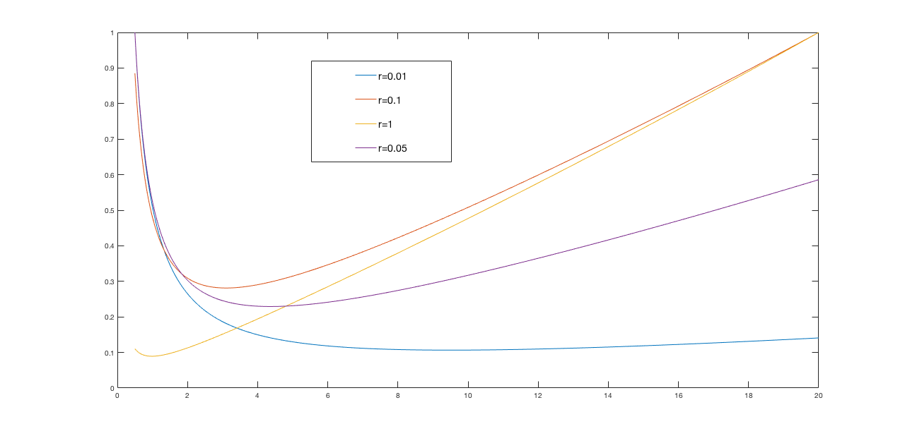
If we set the input weight, \(r,\) to almost any non-zero value, optimizing our cost function will lead to far more reasonable gains. For example, below are normalized plots of the cost function \[ \frac{(q + rk^2)}{1 - (a-bk)^2} \] versus gain (\(k\)) for \(q = 1\) and \(r\) ranging from \(0.01\) to \(1.0\). Notice that the gains associated with minimum of each cost function curve varies from \( k \approx 1.4 \) for the \(r=1\) case, to \( k \approx 11 \) for the \(r = 0.01 \) case.
Have we have learned all we need to know about LQR? The steps for using LQR to find gains are certainly clear enough. They are:
From the above perspective, insisting on a weighted sum-of-squares cost function seems overly restrictive. For example, one could specify problem-specific constraints like: be within one percent of steady-state in seven seconds; limit the motor current to less than 1.5 amps; prevent any states from exceeding twice their initial values. What is wrong optimizing the gains while satisfying such constraints? The answer is that a good formulation is hard to find, much can go wrong. Constraint sets can be impossible to resolve, cost functions can be computationally-intractable to optimize, feasibility checks and/or the cost evaluations can require analyses beyond the canonical initial condition problems. And even if the optimization succeeds, the resulting \(\textbf{K}_{opt} \) could be fragile, meaning that small mismatches between model and system can decimate performance.
In this section, we will use the scalar problem to show that the LQR optimization to determine \(\textbf{K}_{opt}\) is not difficult. In the scalar case, it involves solving a quadratric, but in the vector case, it requires an eigendecomposition. We also introduce another important idea in LQR, that the cost function can be summarized by a state-independent matrix,\(\textbf{P}\).
We showed that the LQR cost function for the canonical example, \[ x[n] = (a-bk)^n x[0], \] is given by \[ \sum_{n=0}^{\infty} \left( q x^2[n] + r u^2[n] \right) = \sum_{n=0}^{\infty} (q + rk^2) x^2[n] = \sum_{n=0}^{\infty} (q + rk^2) (a-bk)^{2n} x^2[0] = p x^2[0] \] where we are introducing the scalar, \(p\), that relates the square of the state, \(x^2[0]\), to the LQR cost function. Note that \(p\) is not dependent on the initial state, \( x[0]\), but does depend on the weights \(q\) and \(r \), the system parameters \(a\) and \(b\), and the feedback gain \(k\). That is a lot of parameters, \(q,r,a,b,k\), but since \(p\) summarizes the relationship between the initial state and the cost to drive that state to zero, it should depend on all the parameters.
As we showed above, when picking feedback gains based on minimizing the LQR metric, the initial state is irrelevent, but \(p\) is important. That is, we are determining the best \( k \) by minimizing \(p\), \[ k_{opt} = k\;\;\; that \;\; minimizes \;\; p. \] For this scalar problem, \(k_{opt} \) is the value of \(k\) that zeros the derivative of \( p \) with respect to \( k \). Or more mathematically, we must solve \[ \frac{dp}{dk} = \frac{d}{dk} \left(\frac{(q + rk^2)}{1 - (a-bk)^2}\right) = 0 \] for \(k\). But do not get out your calculus textbook just yet!!! There is another version of this problem that generalizes to the many state case.
For our scalar case, we were able to determine \( p\) by summing the series generated by the difference equation (assuming that the system is stable) to show that \(p\) is given by \[ p = \frac{(q + rk^2)}{1 - (a-bk)^2}. \] and by cross-multiplying by \( (1-(a-b)^2) \) (as suggested in the discussions), \[ p (1-(a-b)^2) = (q + rk^2) \] which can be reorganized as, \[ p = (q+rk^2) + p(a-b)^2. \] Note that \( p \) appears on both sides of the above equation, and indicates a more fundamental idea Since we will not be able to sum the series when analyzing the vector case, below we will show another approach for deriving the above equation that exposes a more fundamental property about \( p\). But let us address the optimization first.
Since we do not know \(k \), and we do not know \( p \), the above equation might not seem that helpful. But it is, as we can differentiate the equation with respect to \(k\), \[ \frac{dp}{dk} = 2rk + 2\frac{dp}{dk} (a-bk)^2 + 2p(a-bk)(-b) \] which we can simplify since we are interested in the value of \(k \) that minimizes \(p\), and for that value of \(k\), \(k_{opt} \), we know \(\frac{dp}{dk} = 0\). Using the zero derivative, \[ 0 = 2rk_{opt} - 2pb(a-bk_{opt}) \] or \[ k_{opt} = \frac{abp}{r+b^2p}. \]
When we plug the value for \( k_{opt} \) in to the equation for \( p \), we get the well-known Ricatti equation for \(p\) given the \(p\)-minimizing gain. Here, in scalar form, (we let the computer do this algebra), \[ p_{opt} = a^2p_{opt} + q - \frac{(abp_{opt} )^2}{b^2p_{opt} + r}. \] You may wonder why these formulas are any better that just differenting \(p\). The answer is partly that these equations tell you two things, the optimal \(k\) and the cost to drive any state to zero. But the real answer is that the above form of the equations generalizes to the vector case, or it will, once we find an alternative to summing the series.
Suppose we were to ask the question, what is the LQR cost function starting from \( x[1] \)? That is, what is \[ \sum_{n=1}^{\infty} (q + rk^2) (a-bk)^{2(n-1)} x^2[1]? \] Suppose we let \( \tilde{n} = n-1 \), then \[ \sum_{n=1}^{\infty} (q + rk^2) (a-bk)^{2(n-1)} x^2[1] = \sum_{\tilde{n}=0}^{\infty} (q + rk^2) (a-bk)^{2(\tilde{n})} x^2[1], \] but since the upper limit of the summation is infinity, \[ \sum_{\tilde{n}=0}^{\infty} (q + rk^2) (a-bk)^{2(\tilde{n})} x^2[1] = p x^2[1] \]
Extraordinary? We think so. The LQR cost to drive \(x[n] \) to zero, \( p x^2[n] \), DOES NOT DEPEND ON n! Should we be surprised? No. If we are driving from San Francisco to Los Angelos, and want to know how much gas we will need, it does not matter if we started our trip in Oregon or Ottawa.
The history independence of the LQR cost gives us an interesting relationship for p, \[ p x^2[0] = \sum_{n=0}^{\infty} (q + rk^2) x^2[n] = (q + rk^2)x[0] + \sum_{n=1}^{\infty} (q + rk^2) x^2[n] = (q + rk^2)x^2[0] + p x^2[1]. \] We can eliminate \( x[1] \) since\( x[1] = (a-bk) x[0]\), and therefore \[ p x^2[1] = p \left((a-bk)x[0]\right)^2 = p (a-bk)^2 x^2[0], \] which leads us to \[ p x^2[0] = \left((q + rk^2)+ p (a-bk)^2\right) x^2[0]. \] Since the above equation must hold for all possible values of \( x[0] \), we recover the equation for \(p\) from above, \[ p = (q + rk^2) + p (a-bk)^2. \] The equation was telling us about the invariance of \(p\), a property we can use in the vector case.
The input to any physical system we would like to control will have limitations that restrict performance. For example, we may be controlling a system by adjusting velocity, acceleration, torque, motor current, or temperature. In any practical setting, we will not be able to move too fast, or speed up too abruptly, or yank too hard, or drive too much current, or get too hot. And it may even be important to stay well below the absolute maximums most of the time, to reduce equipment wear. In general, we would like to be able to design our feedback control algorithm so that we can balance how "hard" we drive the inputs with how fast our system responds. As we have seen in the heat distribution and turbine control examples, determining \(k\)'s by picking natural frequencies is not a very direct way to address that balance.
Instead, consider determining gains by optimizing a metric, one that balances the input's magnitude and duration with the rate at which states of interest appoach a target value. And since our problems are linear, the metric can be established using a cannonical test problem, simplifying the formulation of the optimization problem. For the canonical test problem, we can follow the example of determining how a turbine's position evolves just after being misaligned by a gust of wind. That is, we can consider starting with a non-zero initial state, \( \textbf{x}[0] \), and then using feedback to drive the state to zero as quickly as possible, while adhering to input constraints. In particular, find \( \textbf{K} \) that minimizes a metric on the state, \( \textbf{x} \), and the input, \( \textbf{u} = \textbf{K} \cdot \textbf{x} \), that satisify \[ \textbf{x}[n] = \textbf{A}\textbf{x}[n-1] + \textbf{B}\textbf{u}[n-1] = (\textbf{A} - \textbf{B}\cdot \textbf{K})\textbf{x}[n-1]. \]
And what is a good metric? One that captures what we care about, fast response and with reasonable input, AND is easily optimized with respect to feedback gains. The latter condition has driven much of the development of feedback design strategies, but the field is changing. Better tools for computational optimization is eroding the need for an easily optimized metric. Nevertheless, we will focus on the most widely used approach, based on minimizing an easily differentiated sum-of-squares metric.
The well-known linear-quadratic regulator (LQR) is a based on solving an optimization problem for a sum-of-squares metric on the canonical problem of driving \( x[0] \ne 0 \) to zero as quickly as possible. The metric for LQR is \[ \min_{\textbf{K}} \left( \sum_{n=0}^{\infty} \textbf{x}^T[n]\textbf{Q}\textbf{x}[n] + \sum_{n=0}^{\infty} \textbf{u}^T[n]\textbf{R}\textbf{u}[n] \right), \] where \( \textbf{Q} \) and \( \textbf{R} \) are \( \#states \times \#states \) and \( \#inputs \times \#inputs \) positive definite state and input weighting matrices. The first term \[ \sum_{n=0}^{\infty} \textbf{x}^T[n]\textbf{Q}\textbf{x}[n], \] generally decreases when states go to zero faster, and the second term \[ \sum_{n=0}^{\infty} \textbf{u}[n]\textbf{R}\textbf{u}[n] = \sum_{n=0}^{\infty} (\textbf{K} \cdot \textbf{x}[n])^T\textbf{R}(\textbf{K} \cdot \textbf{x}[n]) = \sum_{n=0}^{\infty} \textbf{x}^T[n] \textbf{K}^T \textbf{R}\textbf{K} \textbf{x}[n]) \] generally increases when inputs have larger magnitudes and last longer.
By changing \( \textbf{Q} \) and \( \textbf{R} \), one can trade off input "strength" with speed of state response, but only in the total energy sense implied by the sum of squares over the entire semi-infinite interval. In order to develop an intuition that helps us pick good values for \( \textbf{Q} \) and \( \textbf{R} \), we will consider simplified settings, starting with the scalar turbine problem.
This question is about the linear algebra associated with LQR regulation. It might be worth coming back to this problem AFTER you have read the scalar example in the next section.
Suppose we apply the sum-of-squares metric to a single-input canonical test problem, \[ \textbf{x}[n] = \textbf{A}\textbf{x}[n-1] + \textbf{B}u[n-1] \] where \(u[n] = -\textbf{K}\textbf{x}[n],\) and the initial condition is \( \textbf{x}[0] \). We claim that in this case, the sum-of-squares metric \[ \left( \sum_{n=0}^{\infty} \textbf{x}^T[n]\textbf{Q}\textbf{x}[n] + \sum_{n=0}^{\infty} \textbf{u}^T[n]\textbf{R}\textbf{u}[n] \right), \] can be reduced to the form \[ \textbf{x}^T[0] \textbf{P}\textbf{x}[0] \] where \( \textbf{P} \) is a \( \#states \times \#states \) matrix that depends on \( \textbf{A},\) \(\textbf{B},\) \(\textbf{Q},\) \(\textbf{R},\)and \(\textbf{K}\).
The matrix \( \textbf{P} \) is going to play an important role, because it tells us the cost to drive \( \textbf{x}[0] \rightarrow 0 \) with respect to the LQR metric. Considering its form is worth thinking through carefully.
Which of the following is true about \( \textbf{x}[n] \) and \( \textbf{x}^T[n] \) for this feedback problem with initial condition only.
Which of the following is true about \( \textbf{u}^T[n]\textbf{R}\textbf{u}[n] \) for this feedback problem with initial condition only.
Which is true about \[ \left( \sum_{n=0}^{\infty} \textbf{x}^T[n]\textbf{Q}\textbf{x}[n] + \sum_{n=0}^{\infty} \textbf{u}^T[n]\textbf{R}\textbf{u}[n] \right)? \]
If \[ \left( \sum_{n=0}^{\infty} \textbf{x}^T[n]\textbf{Q}\textbf{x}[n] + \sum_{n=0}^{\infty} \textbf{u}^T[n]\textbf{R}\textbf{u}[n] \right) = \textbf{x}^T[0] \textbf{P}\textbf{x}[0], \] what is true about \( P \)?
In the above problem, we stepped you through the manipulations to determine the \(\textbf{P}\) matrix, which is the higher dimensional equivalent of the scalar \( p \) we described in the first-order section. Given an initial state \( \textbf{x}[0]\), the cost to drive that initial state to zero is given by \[ \textbf{x}^T[0]\textbf{P}\textbf{x}[0]. \] To find the LQR gains, we differentiate \( \textbf{P} \) with respect to the gain matrix \(\textbf{K}\), and then solve for the gains that zero the derivative. But, as mentioned in the first-order section, the exact process involves generating a Ricatti equation, and we are still working on that part of the notes.
You can try using LQR to find gains for several problems from this section, including the heating distribution problem and the turbine problem. If you download the python code in the file lqr_examples.py , and run it, you will see a comparison of deadbeat control and LQR control for the heating distribution system (just close the plot window after it shows you the deadbeat control case, and then it will show you the LQR case). If you try redoing the heat distribution example at the beginning of this LQR section, you will see it that setting state weights makes it far easier to determine gains that will satisfy the constraints. Try doubling the weights on the first and last state in the thermal problem (one at a time) and look at the effects.
You can change examples by changing the string at the top of the file (see below). It is distributed to run the thermal example, but you can also run two versions of the turbine example, or add your model for the propeller arm and use it to pick gains for you.
    #Pick example from thermal, turbine1 and turbine2

Example = 'thermal'
You can change the state and input weights (near the middle of the file), the most interesting ones are the diagonals of the \(\textbf{Q} \) matrix, which weight the individual states. The off-diagonals weight the coupling between states, and their effect can be difficult to interpret.
 #cost matrices for LQR.  REMEMBER PYTHON INDEXES FROM ZERO

# The weight for the first state is Q[0,0].

Q = np.eye(N)

Q[0,0] = 2

R = 1*np.eye(1)