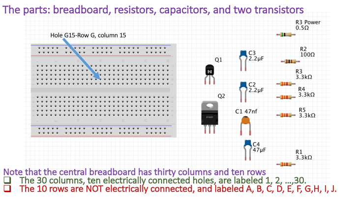
The propeller-arm assembly will consist of the following electrical parts:.
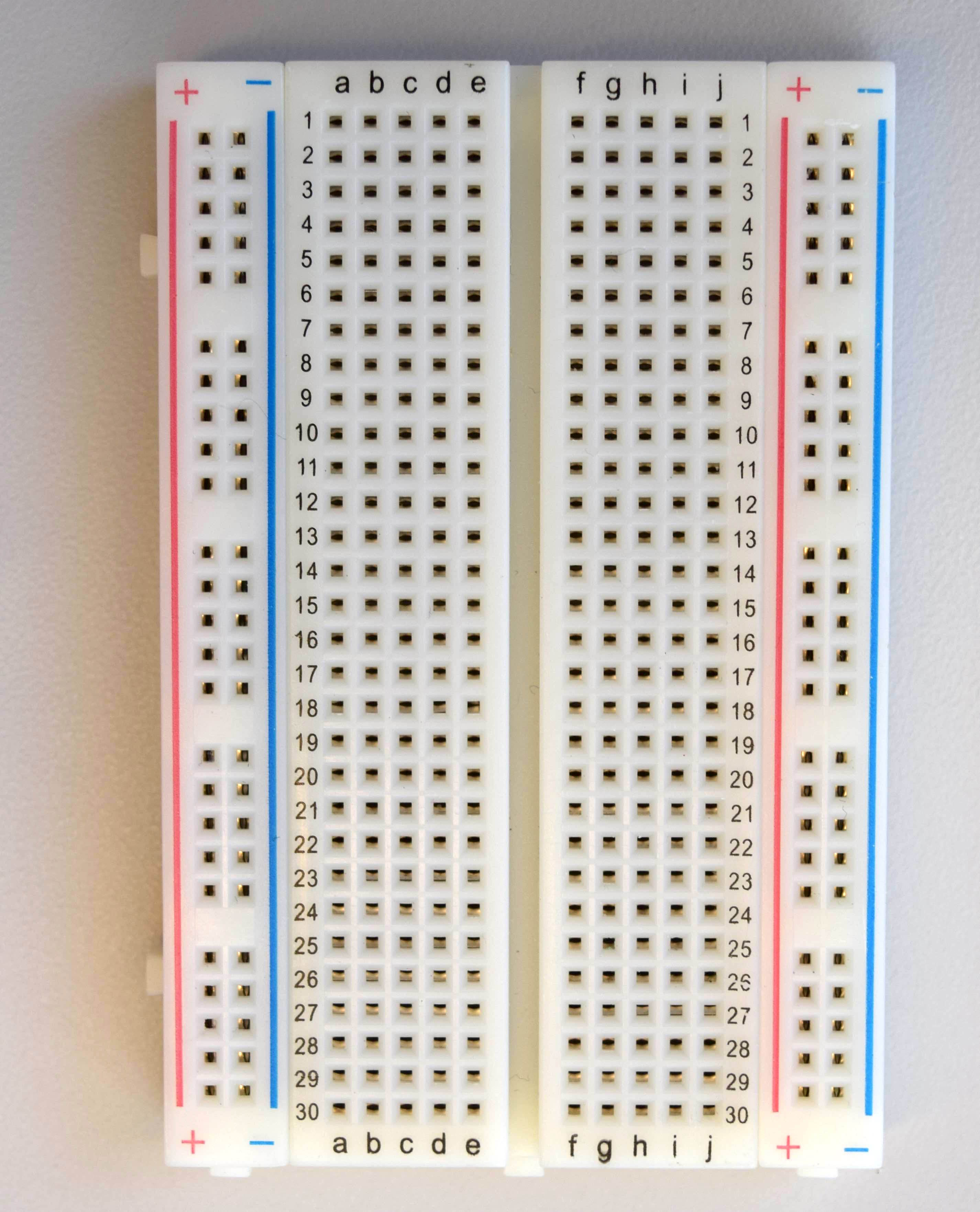
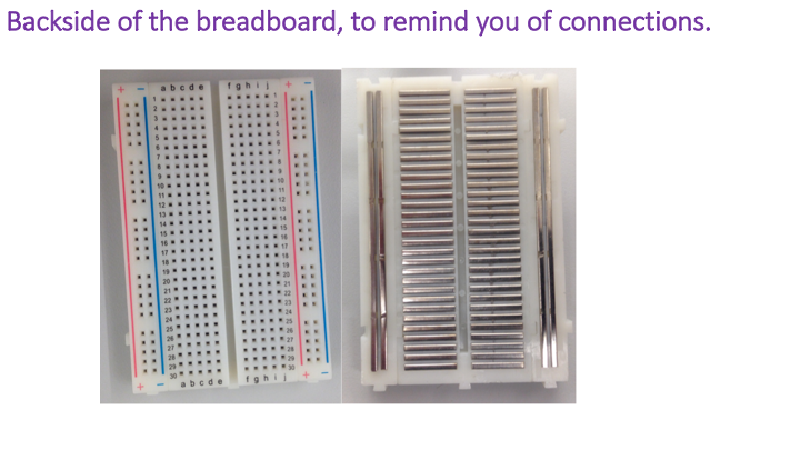
The above prototyping breadboard is a convenient way to connect electrical components together to make a circuit, while also holding the components securely in place. When wires or metal leads on components are inserted in to the holes, they are "grabbed" by metal clips that are electrically connected in groups. The clips are connected together either in rows of five, or in four long columns spanning the entire length of the breadboard. When multiple wires or leads are inserted in to holes in the same row, or the same long column, they become electrically connected. In this way, we can conveniently connect (and hold together) parts.
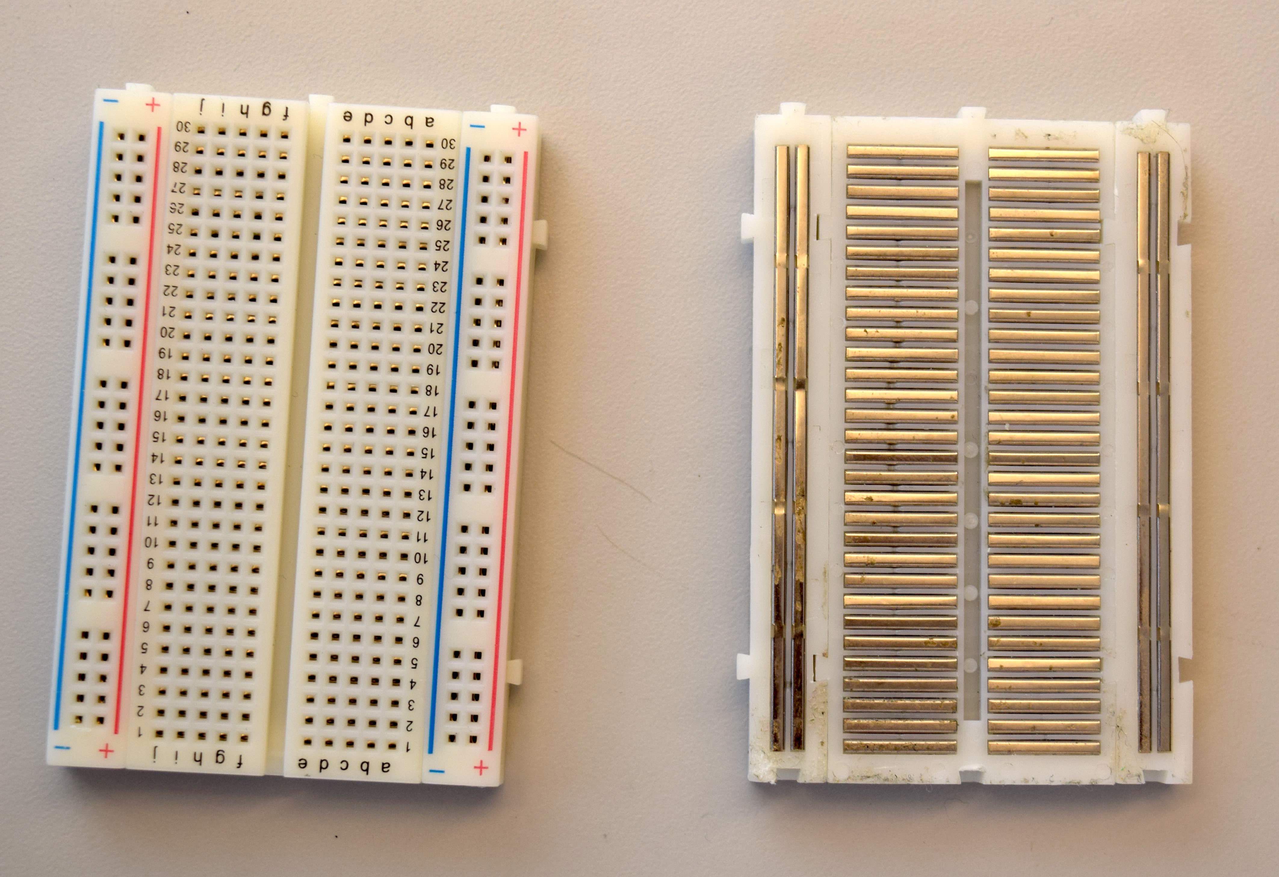
The breadboard has an easily-removed thin paper backing, and underneath that backing is a sticky coating that can be used to attach the breadboard to a firmer surface (such as the floor of the plastic project box). We strongly recommend you attach your breadboard to the floor of the box or to another hard surface. Otherwise, thicker wires or component leads can push the metal clips through the soft backing instead of being "grabbed". No electrical contact will be made, and the circuit will fail.
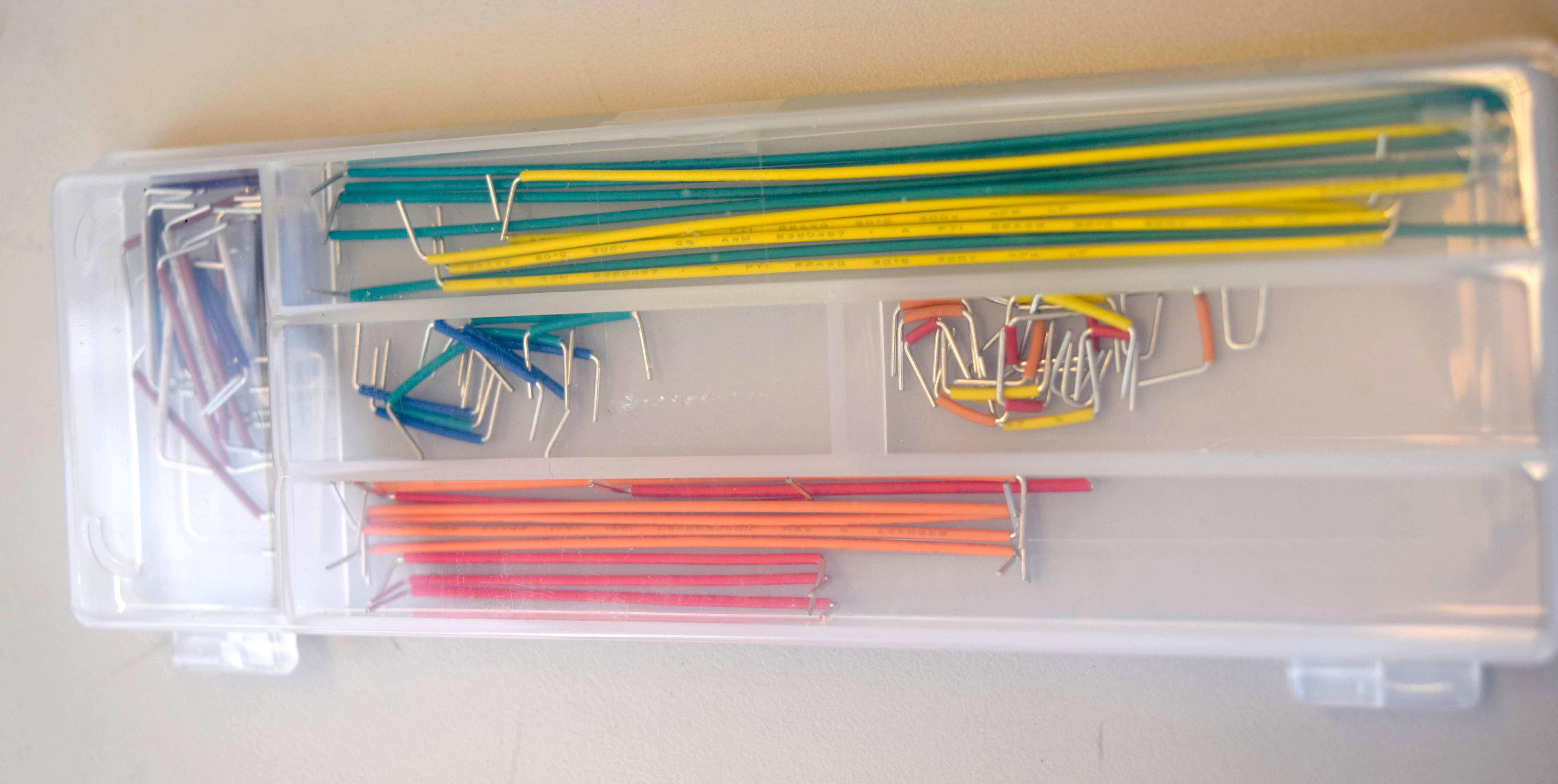
Wires are used to make electrical connections between components that can not be placed in the same row or long column. We use three types of wires in the copter-levitated arm circuitry: prestripped wires for connecting breadboard rows together, male-to-male jumpers wires for making longer distance connections between the breadboard and the microcontroller or the copter, and female-to-male jumper wires for making connections between the breadboard and the angle-sensing potentiometer. The kit of prestripper wires is shown below (we will use the short orange, yellow and blue wires from the kit).
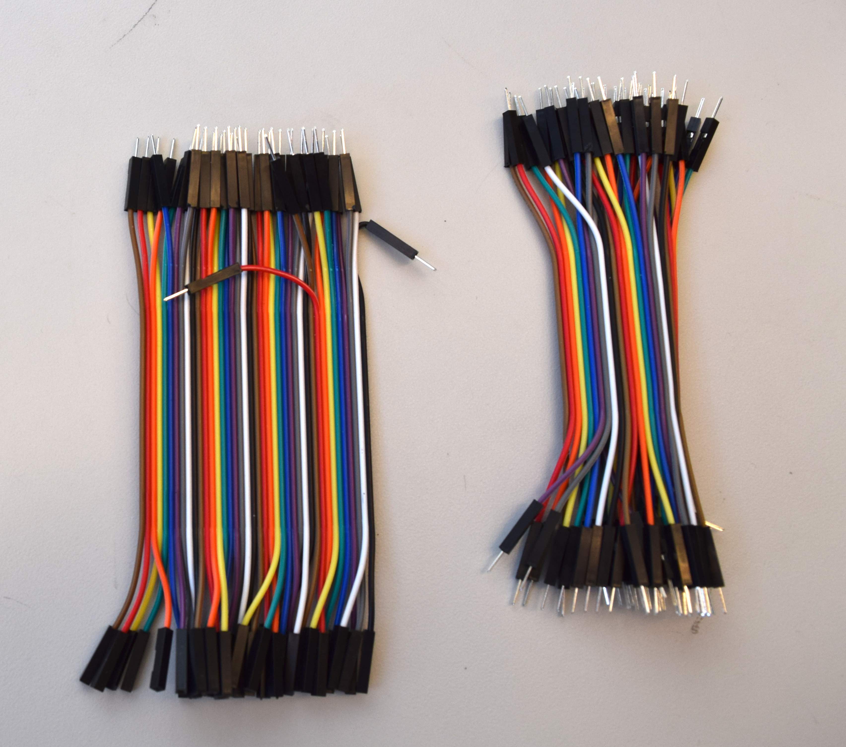
The sets of female-to-male and male-to-male jumpers wires are shown below (female-to-male on the left, and male-to-male on the right). The sets of jumpers are easily pulled apart, in to single jumpers, or in to sets of several jumpers. If you strip the insulation off these jumper wires, you will see that the metal wire is stranded. Jumpers made with stranded wire are more flexible than solid wire jumpers (solid wire is used for the jumpers in the kit above), and can tolerate repeated bending, such as when the arm moves up and down.
Schematically, breadboard and jumper wire connections are represented by lines:

Like any physical potential, voltages in a circuit must be specified with respect to a reference, and that reference is referred to as "ground". By definition, ground has a voltage of zero, and in most circuits, many components are connected directly to ground. For this reason, we assign one of the long collumns of connection points on the breadboard to be ground, and in a schematic, connections to ground are indicated with a special symbol:

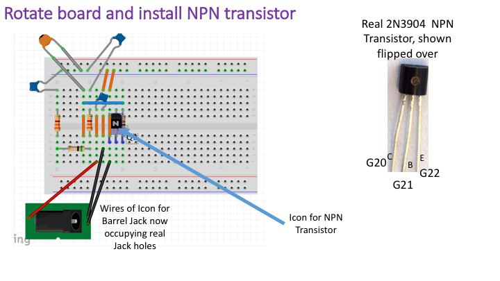
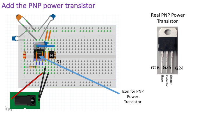
We use two different types of transistors in our circuit. We use a general purpose NPN transistor capable of switching one hundred milliamps of current, the 2N3904 (a classic), to drive a power PNP transistor capable of switching several amps of current, the D45H11. The poower transistor is much larger and has a metal tab with a hole in it. The metal tab helps dissipate heat, and the hole in the tab can be used to connect the tab to a larger metal heat sink. The two transistors are shown below, with the NPN on top and the power PNP on the bottom. IN the picture, the NPN's flat side is facing away, as is the PNP's tab side.
Our NPN transistor (the small one) is represented using the schematic below. With the transistor flat side facing you (so that you can read the text on the transisor), the leads are, from left-to-right, the emitter (E), the base (B) and the collector (C). These pins are shown in the schematic representation:


NOTE that the transistors must be connected EXACTLY as specified in the assembly document.
Three different values of resistors are used for both 6.302.0x and 6.302.1x, and a fourth value of resistor is used only for 6.302.1x (to scale voltages for the different microcontroller). There are four 3300 ohm, or 3.3K ohm, resistors (labeled with orange-orange-red color bands), two of which are used in two low-pass resistor-capacitor filters, one is used to limit the current in to the base of the NPN transistor, one is used to limit the copter indicator LED. The one 100 ohm resistor (labeled with brown-black-brown color bands) is used to limit the current in to the base of the power PNP transistor. There is also a large power resistor (green in color), a 0.5 Ohm 2W resistor. This resistor is used to both limit the current in to the copter motor and to provide a voltage measurement of the motor current. For 6.302.1x, there are two additional 6800, or 6.8k, ohm resistors (labeled with blue-grey-red color bands) used to scale voltages for the Teensy microcontroller. The resistor values are not interchangeable! If you use the wrong resistor value, the circuit will almost certainly not work as intended, and could even DAMAGE your parts. Check the values carefully!!
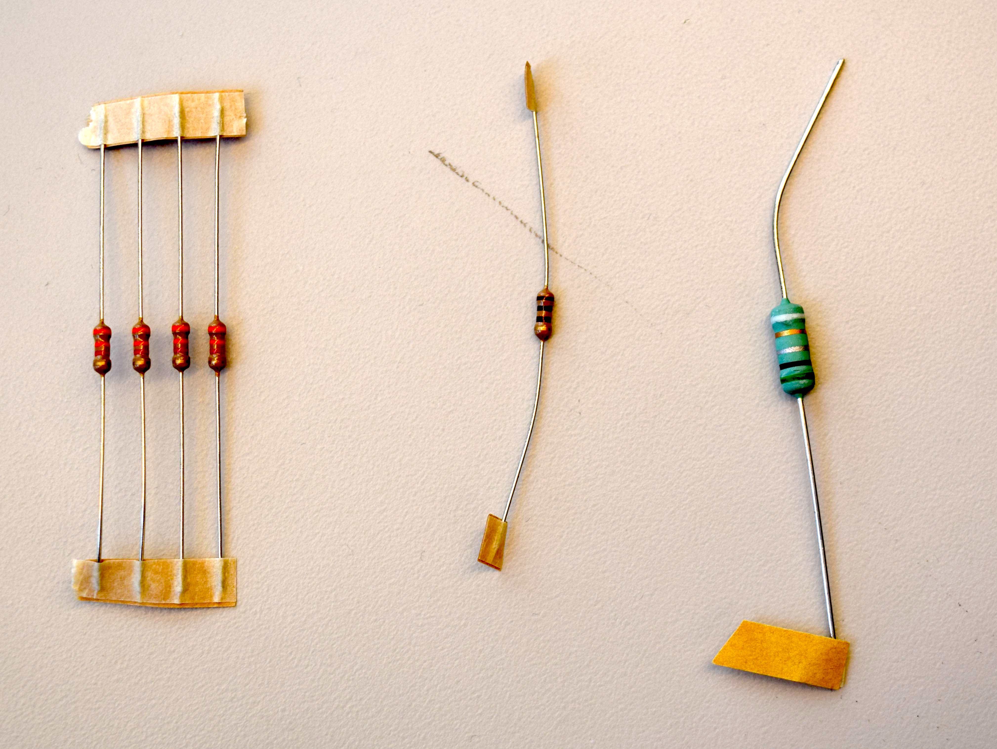
The schematic symbol for a resistor is a zig-zag shape, and is usually accompanied by a label or a value. Resistors are non-polar devices, meaning that their two leads are interchangable. The resistors used for the 6.302.0x are shown below, and are, from left to right, four 3.3k ohm resistors, one 100 ohm resistor, and one 0.5 ohm 2 watt resistor:

We use three values of capacitors in the circuit:
The interpretation of the three digit labels are: \(47\times10^6\) picoFarads or 47 microFarads, \(22\times10^5\) picoFarads or 2.2 microFarads, and \(47\times10^3\) picoFarads or 0.047 microFarads. The capacit .The capacitors are shown below, and are, from left to right, two 2.2uF capacitors (to filter motor signals), one 47uF capacitor (to filter the external power supply), and one 0.047 uF capacitor (to limit the PWM switching speed of the motor current).
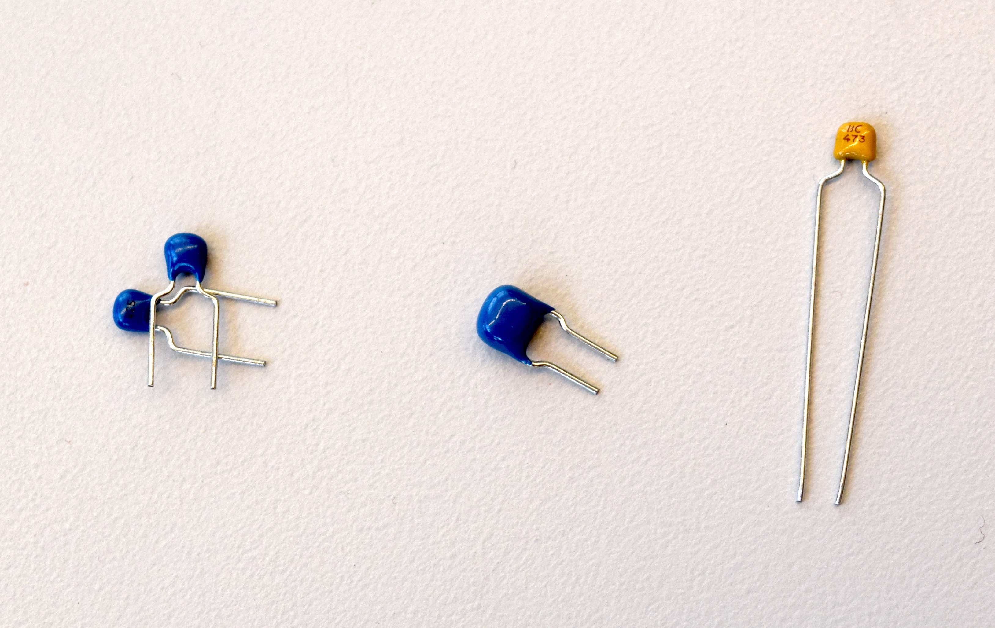
The schematic symbol for a capacitor is a pair of parallel lines, as shown below, and is a reminder that originally, capacitors were made using parallel metal plates. Our capacitors are non-polar, meaning the leads are interchangable, but this is not always true for capacitors. Electrolytic capacitors are polarized, and can actually pop if connected backwards, so we did not use themn in the this project.

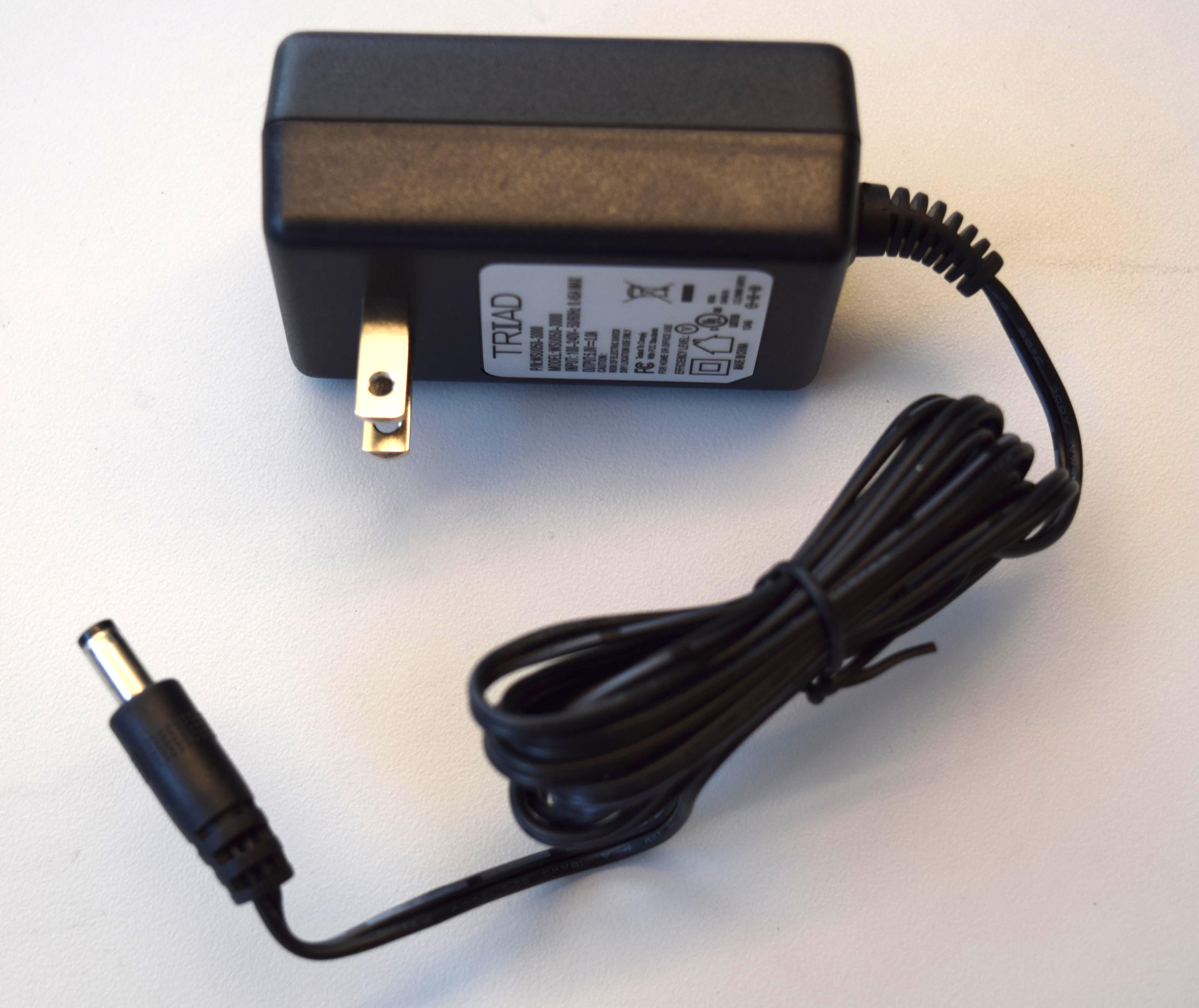
The current for the copter motor can exceed two amps, and is provided by an external five-volt three-amp power supply that plugs in to an outlet (sometimes such power supplies are referred to as "wall worts" because they stick out from the wall when plugged in). Most of the copter driver circuit uses the external five-volt supply, but the angle sensor potentiometer is supplied seperately with power from either the Arduino or the Teensy microcontroller. The reason for seperating the copter power supply from the sensor power supply is that the copter generates an enormous amount of power supply noise, and we wish to isolate the angle sensor from that noise. The power supply is shown below:
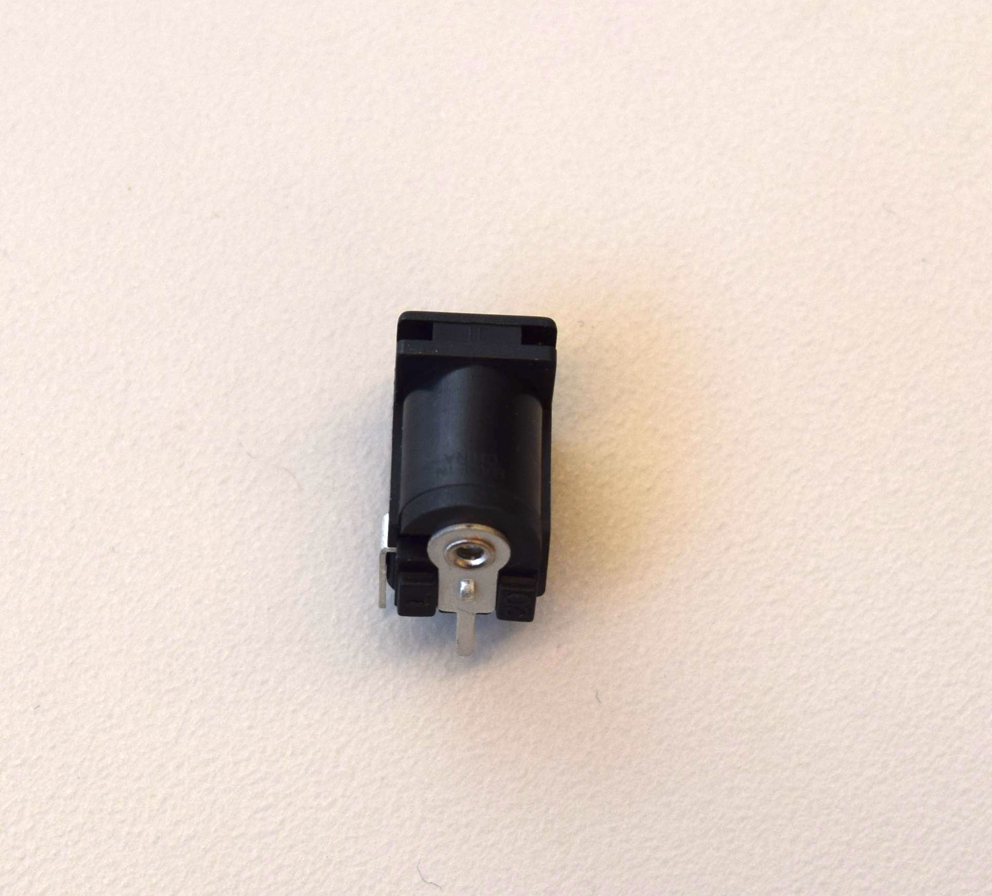
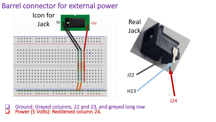
The external power is connected to the breadboard using a 5.0 mm barrel jack with breadboad pins, as shown below. The two pins nearest the opening of the jack are connected to ground, the pin at the opposite end of the opening is the five-volt pin.
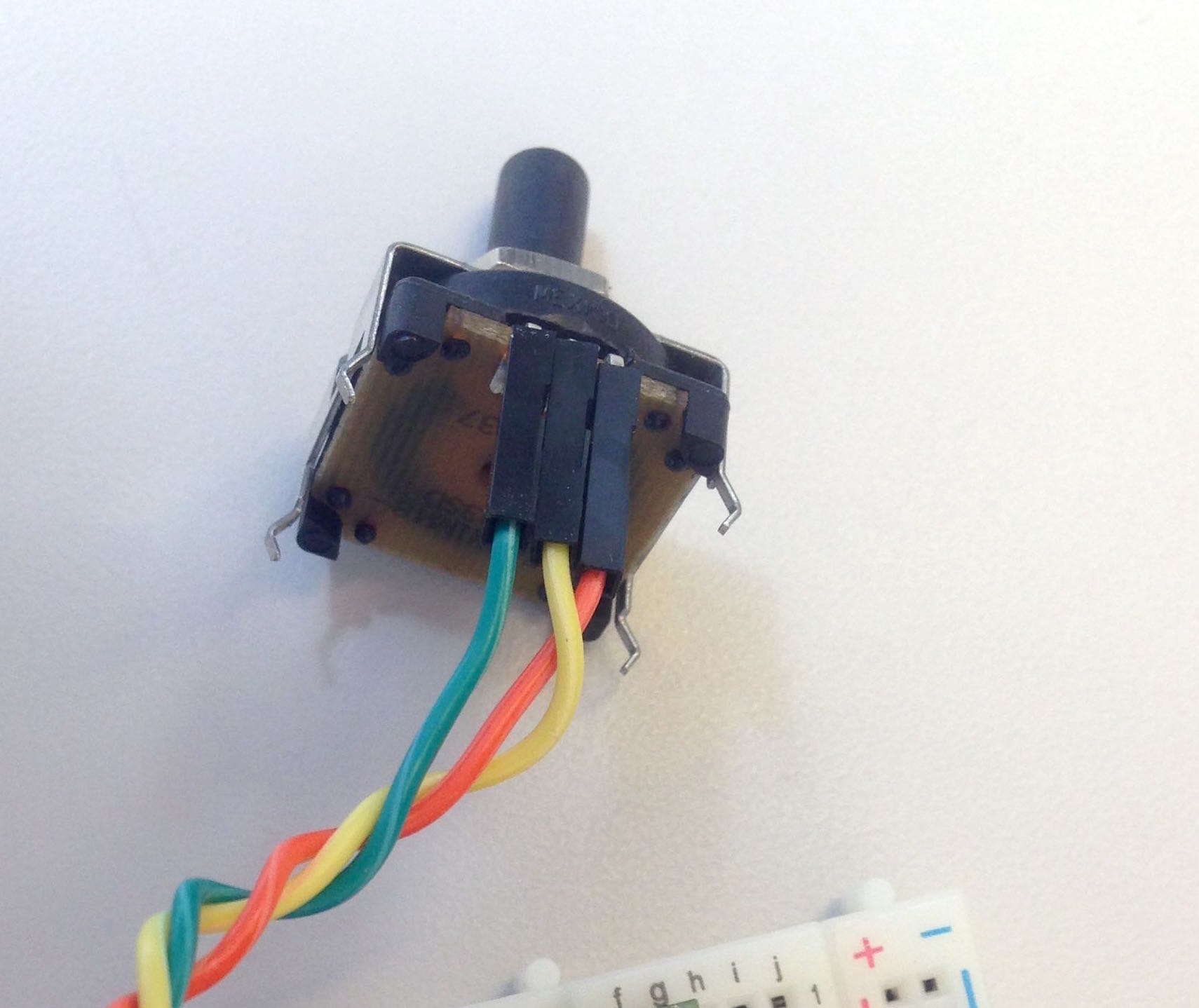
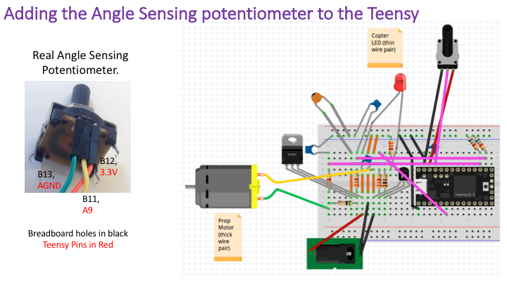
We will use a low-friction potentiometer manufacturered by Honeywell (or Bournes) as an angle sensor. The potentiometer is comprised of a ring of resistive material and wiper contact that rotates with the potentiometer shaft. When the two ends of the resistive ring are connected to ground and a reference voltage (five volts on the Arduino, 3.3 volts on the Teensy), the voltage on the wiper will track the rotation angle of the potentiometer. So when the potentiometer shaft is attached to the copter arm, the wiper voltage can be used to sense the arm angle. The potentiometer is shown below, note that the wiper is the center of the three connection leads.
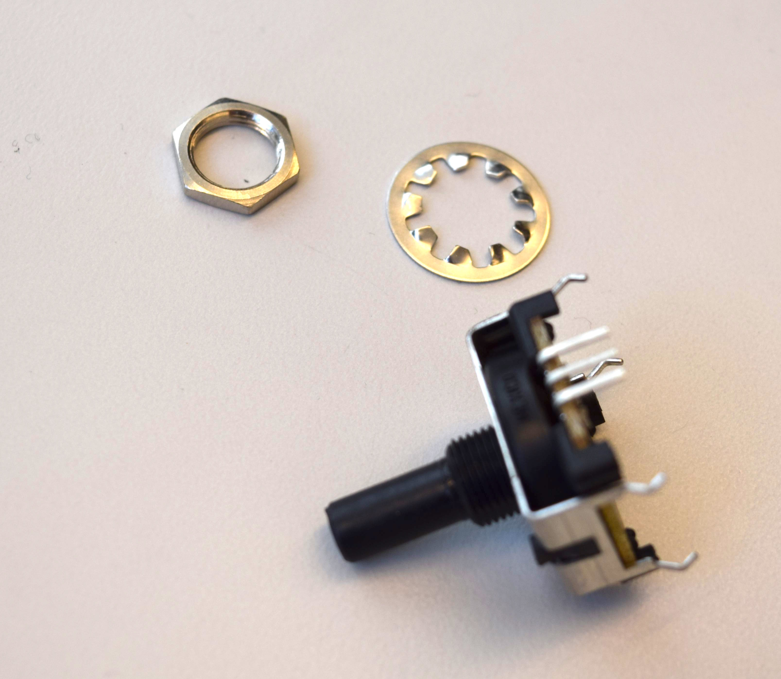
The schematic symbol for a potentiometer is shown below, with the arrow indicating the wiper.

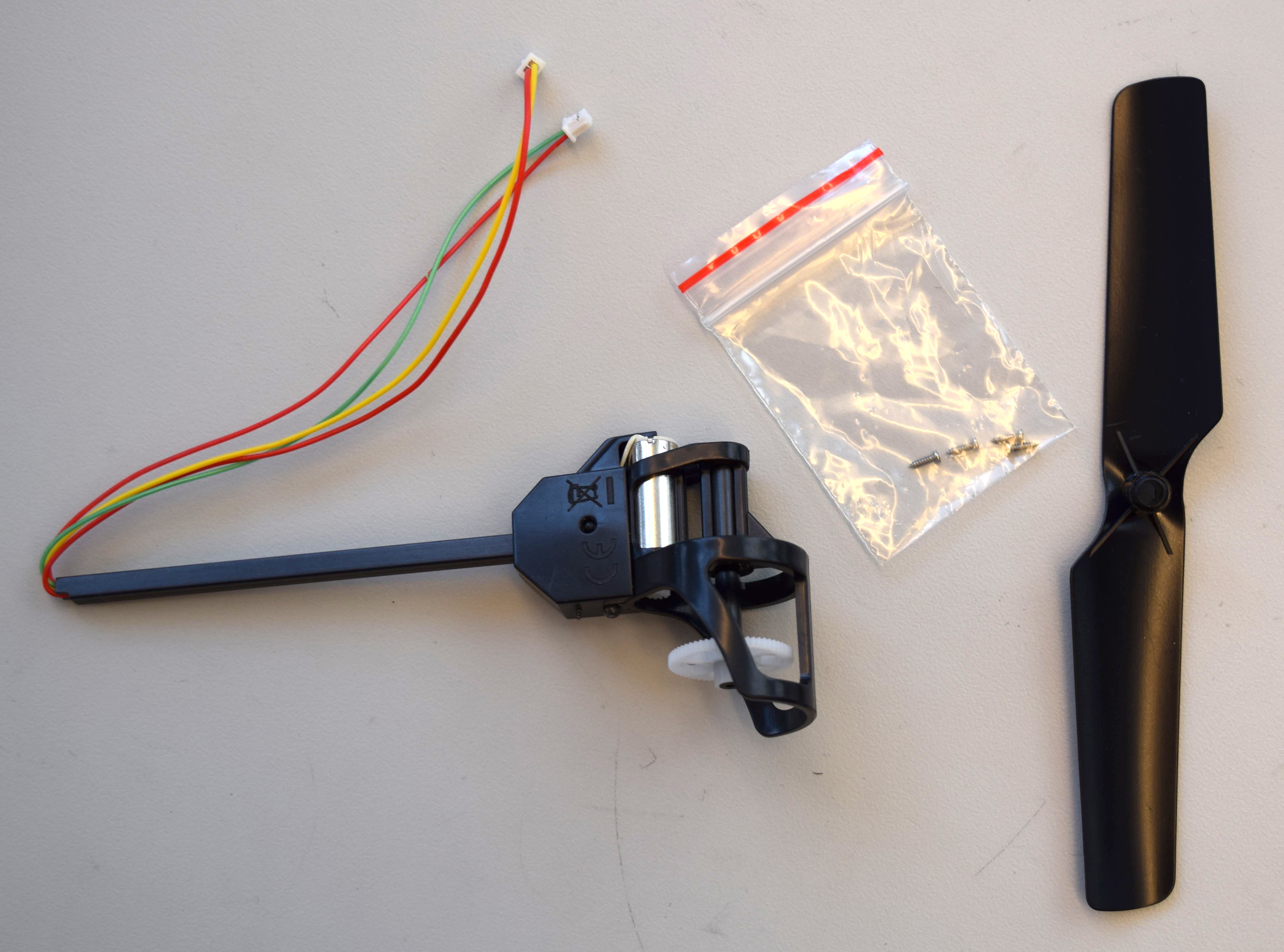
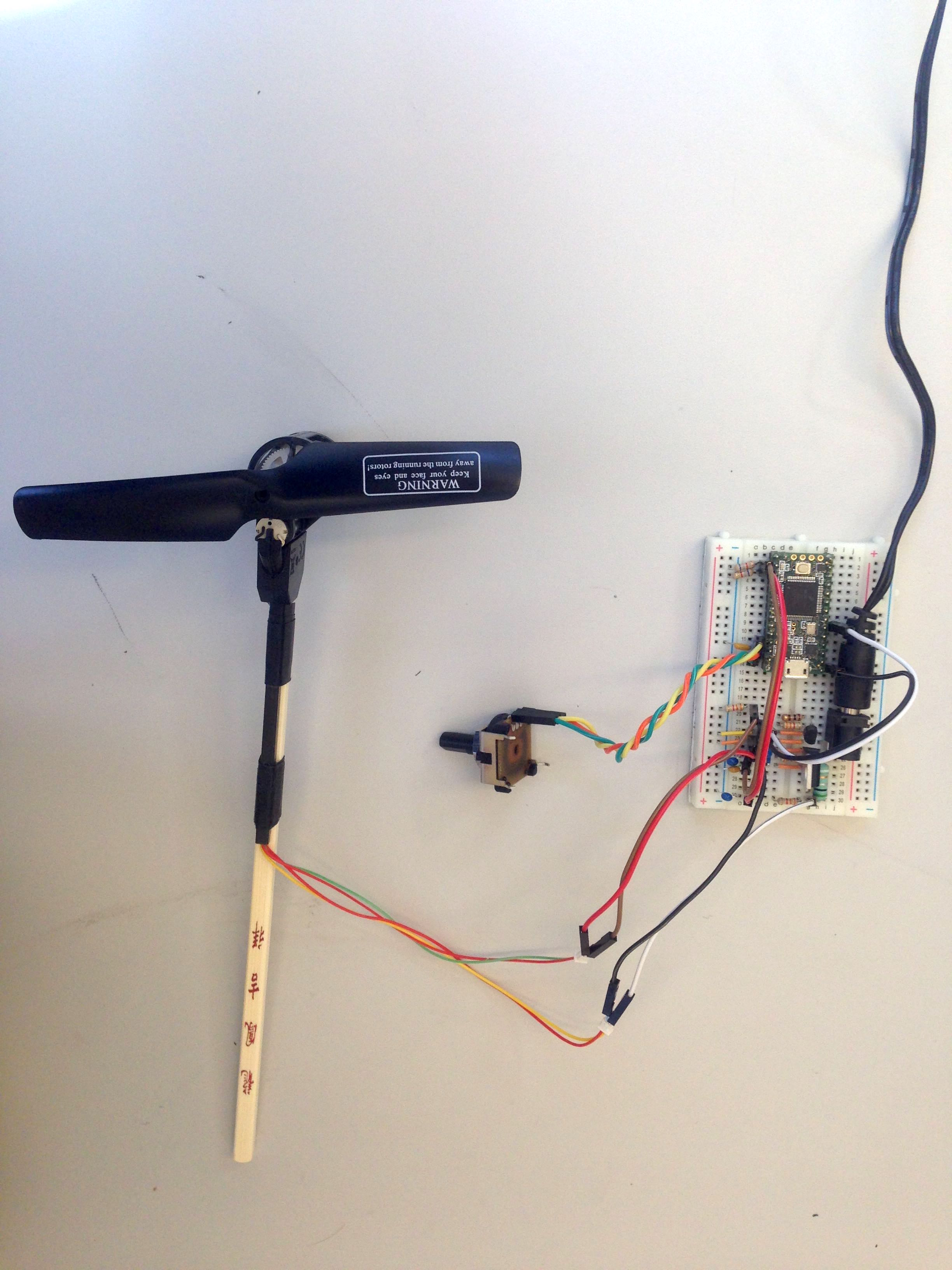
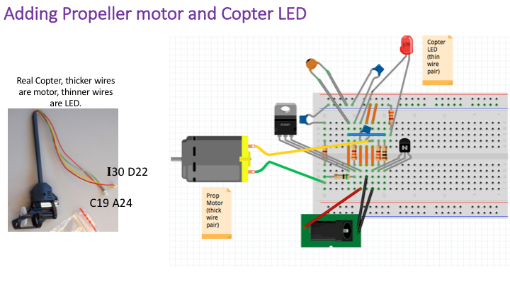
The copter assembly shown below has a power-indicator LED, a power-hungry motor, and a plastic propeller. There are two two-pin connectors terminating two pairs of wires on the copter assembly, the thicker pair of wires is attached to the motor and the thinner pair is attached to the LED. one connected to a pair of very thin wires, and one connected to a pair of thicker wires.
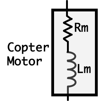
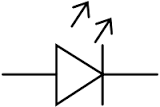
The schematic we used for the motor is indicative of how we model the motor, it is a box with a resistor in series with an inductor, shown on the left in the figure below. On the right, we show the schematic for an LED.
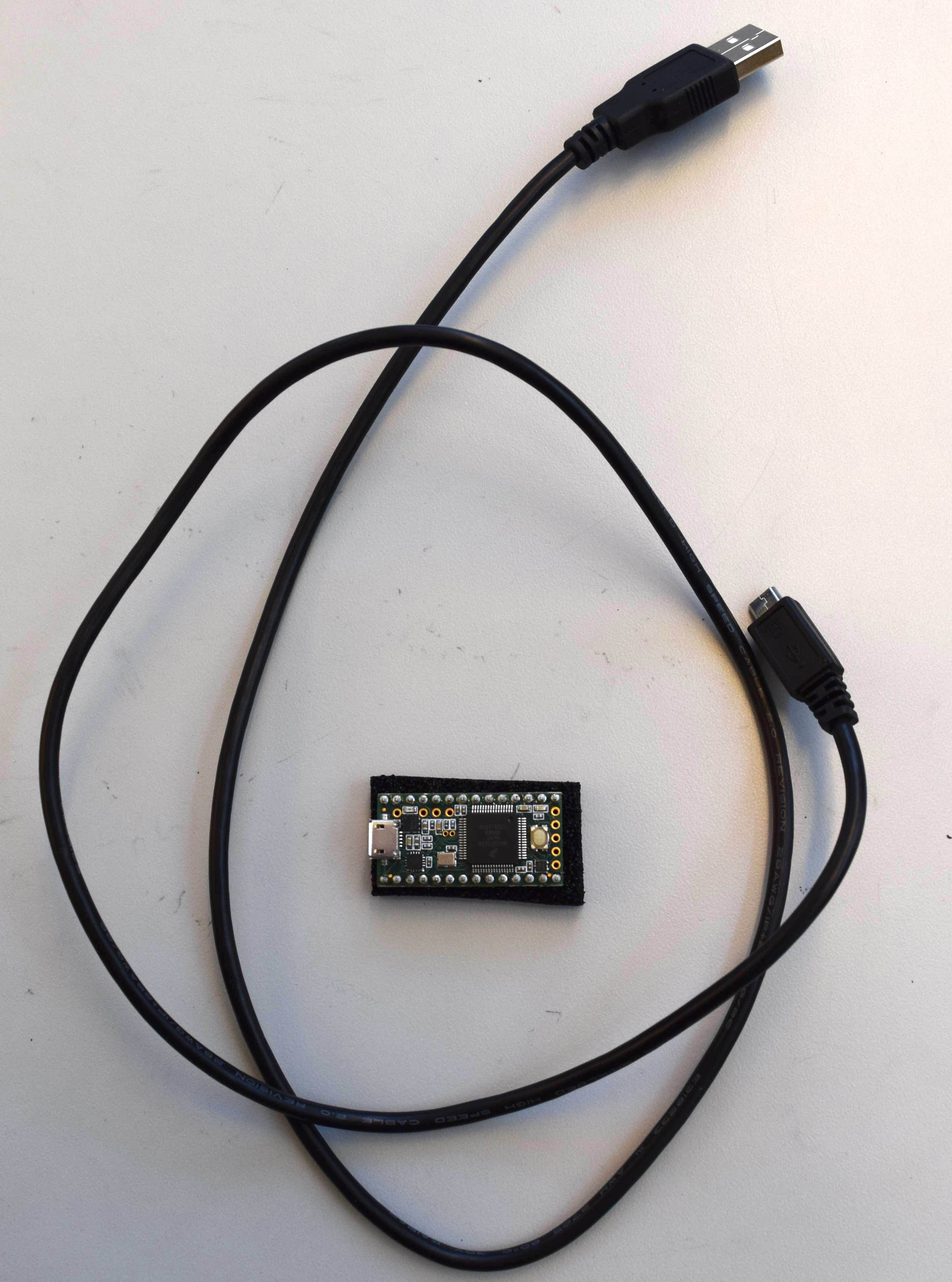
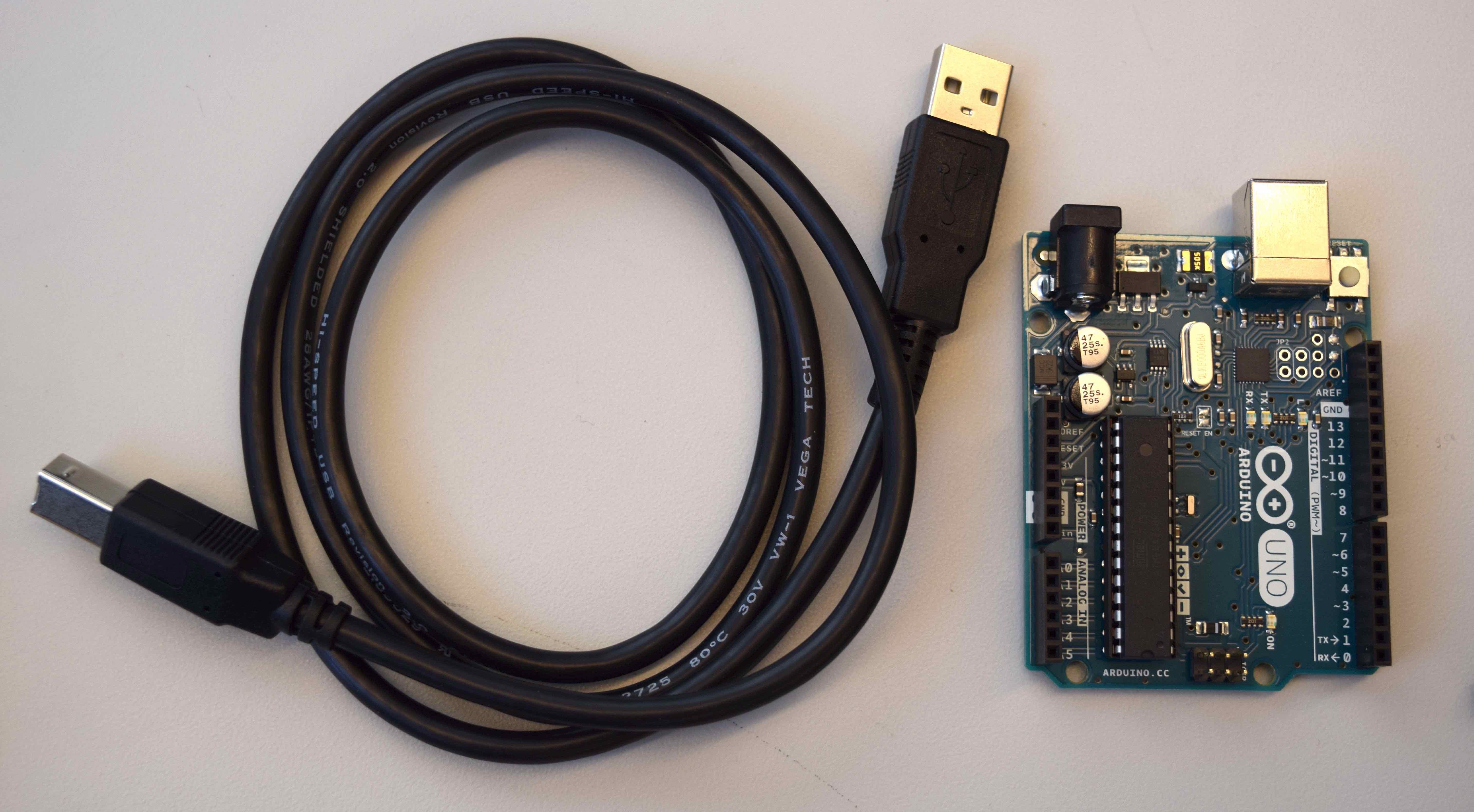
The bulk of our controls and changes and experiments will be implemented in code which we run on our microcontroller. We've designed this course to work with the open-source Arduino/Genuino Uno shown below (right) because it is supported on all major operating systems, is open source, and is very widely available. We will also provide code compatible with the Teensy 3.2 (shown below left) which is a more powerful, more recently developed microcontroller. We are using the Teensy 3.2 in our 6.302.1x course where we investigate state space methods.
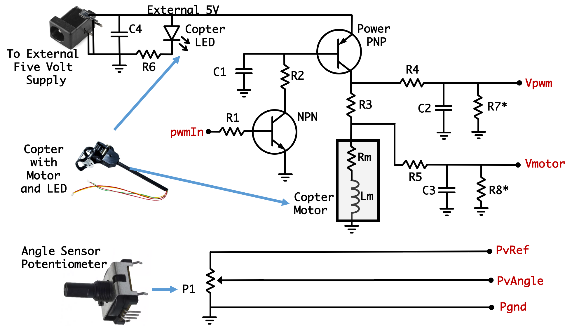
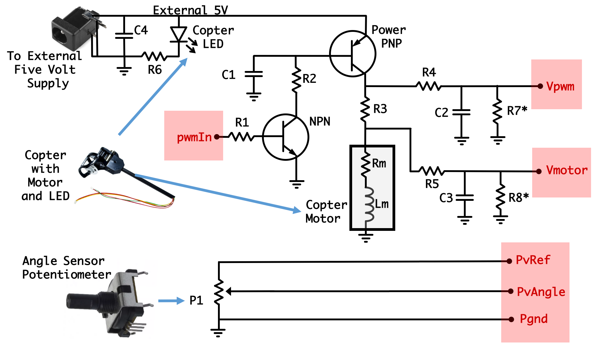
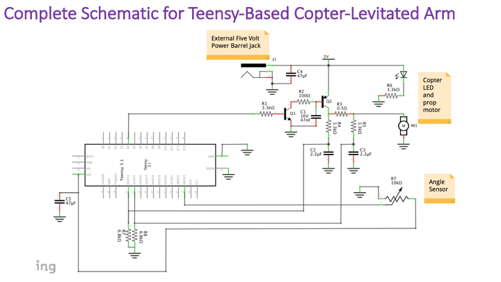
Overall our system circuit is the following:
R2 = \( 100 \Omega \) (brown-black-brown),
R3 = \( 0.5 \Omega \) (green-black-silver, and larger).
R1 = R4 = R5 = \(3.3K\Omega \) (orange-orange-red),
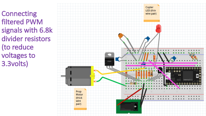
R7* = R8* = \(6.8K\Omega \) (blue-grey-red) and used for Teensy Only!!
Now don't freak out if you've never built anything before from a schematic. We have plenty of pictures and we've tried to make the design as simple as possible so that if you want to go ahead and build it from schematic you totally can, but if you want to copy our wiring from the pictures that's totally great too! As a combination you can use the way we wired it and the schematic to maybe get some practice with some good breadboarding techniques (keeping short wires, making your connections as direct as possible especially on high-current pathways, etc...)
There are two microcontrollers we are actively supporting this time on 6.302.0x, the Arduino Uno and the Teensy 3.2.
This Assembly Video starting at 10 s
The next part we need to prep is the potentiometer, which we'll use as an angle sensor.
Assembly Video at 1:41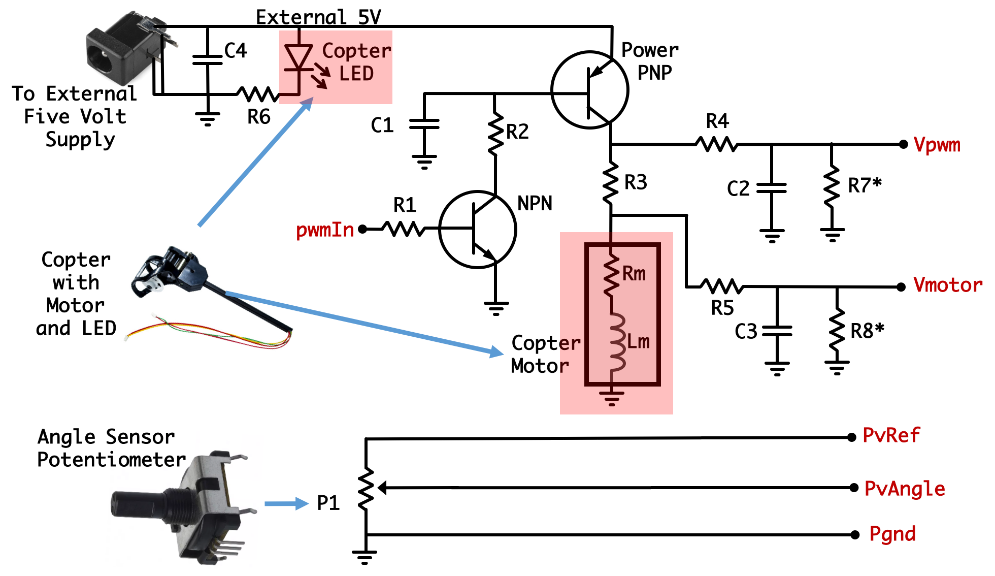
As shown in the assembly video, using a pair of scissors and periodic manual size comparison of the potentiometer drill out a hole in the short end of the box about two-thirds of the way from the bottom of the box between two of the notch-slots.
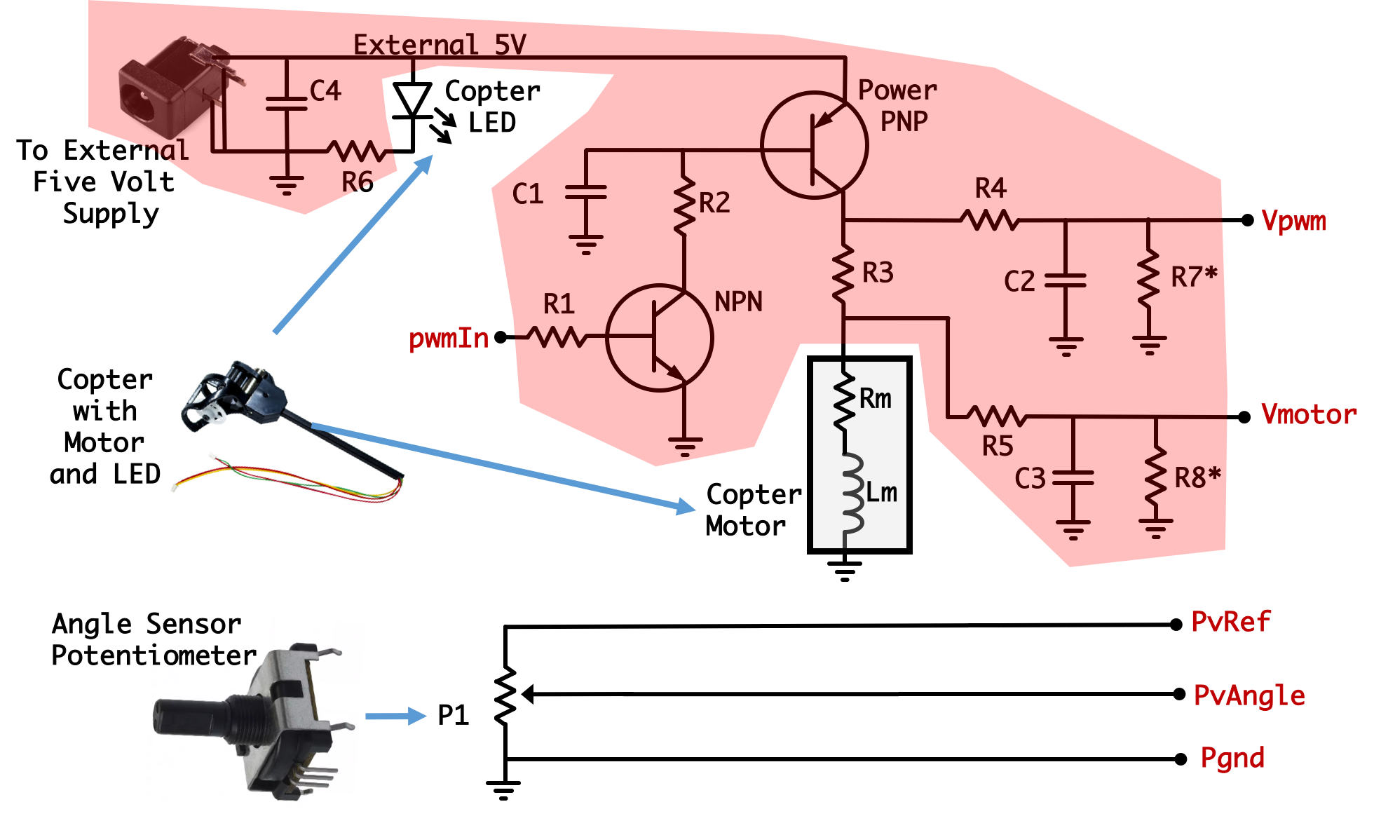
Right at 9:59 in the Assembly Video Jacob takes a wire and connects the node called pwmIn to the 5V supply. What this does is manually turn on the NPN transistor, which subsequently turns on the PNP power transistor which then drives the propeller motor! You can see in the video Jacob is tapping the connecting wire to the back of the power jack which is at 5V to achieve this
The next part we need to prep is the potentiometer, which we'll use as an angle sensor.
Assembly Video at 2:18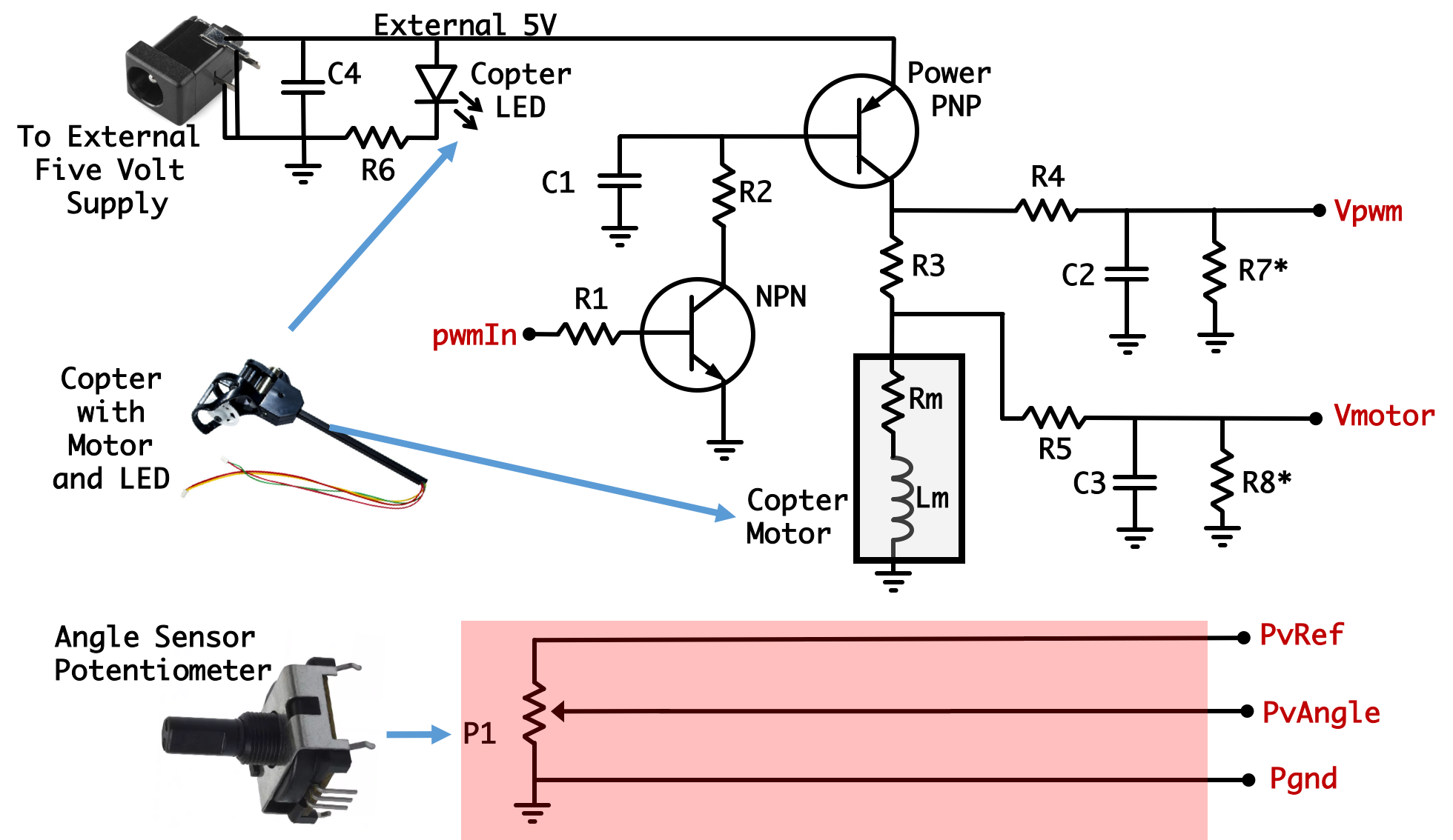
As shown in the assembly video, using a pair of scissors and periodic manual size comparison of the potentiometer drill out a hole in the short end of the box about two-thirds of the way from the bottom of the box between two of the notch-slots.
Attach three Female-to-Male wires to the potentiometer and twist them like shown. It is very important to tightly twist the three wires together. By doing so, any noise will be picked up by all three wires in the same way, leading to at least partial cancellation.
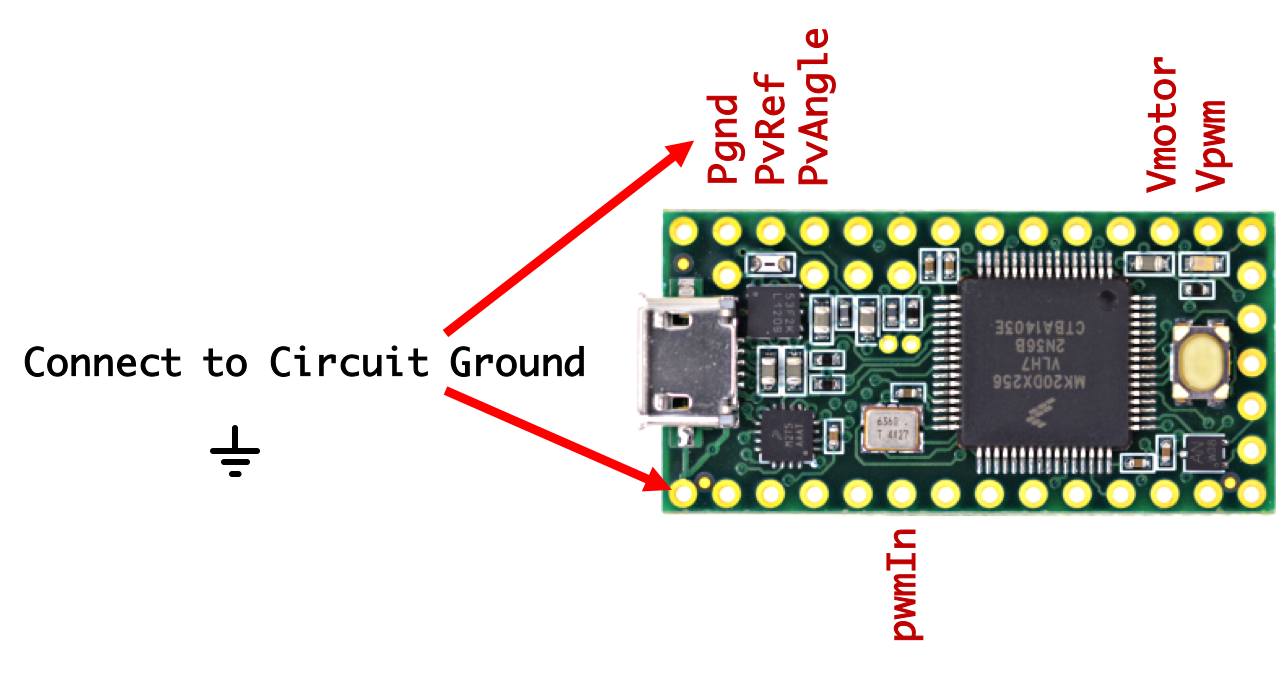
The last remaining part in our assembly journey is interfacing our circuit with the microcontroller of choice. The following nodes in our circuit need to be wired up to it
Based on what your microcontroller is (we're assuming a Teensy 3.2, friends), move onto the next section to discuss wiring for the specific board.
The Teensy 3.2 is small enough to be directly fit into the left half of our breadboard. A full video of the Teensy 3.2 being incorporated is found here. Use this video for reference while reading the instructions below:
The Teensy should be placed as close to the edge of the breadboard as possible with its USB micro connector facin the rest of the components. To interface with the rest of the circut, the following Teensy 3.2 pins need to be connected:
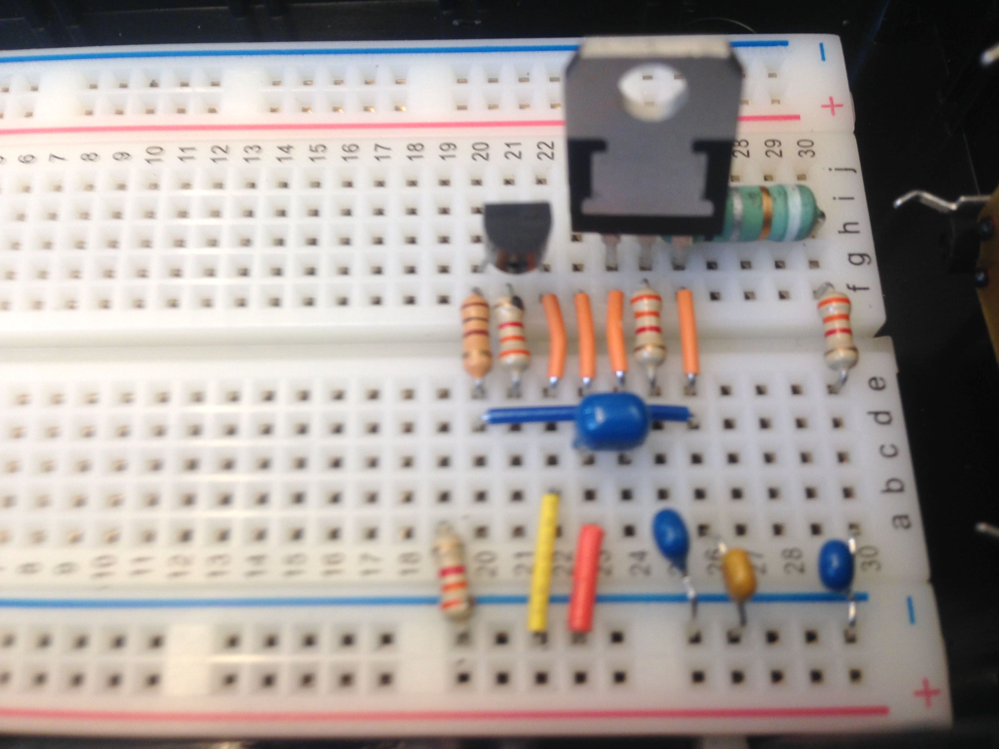
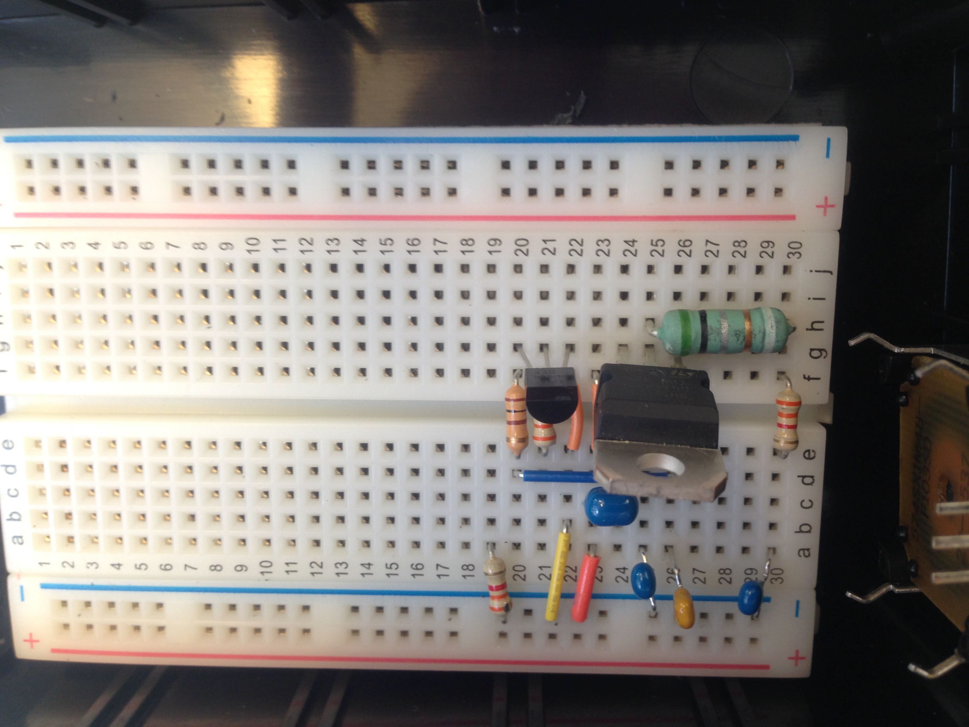
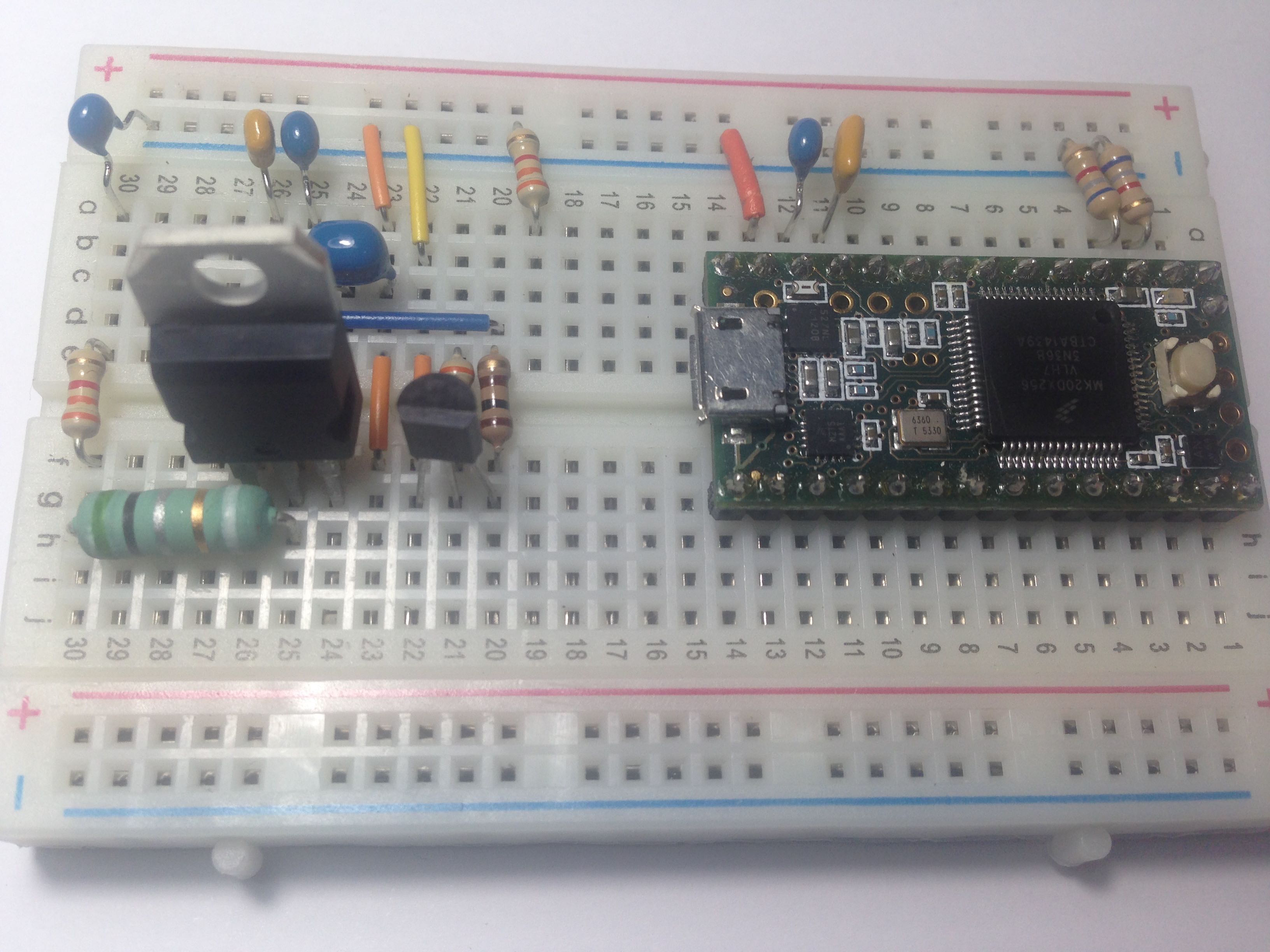
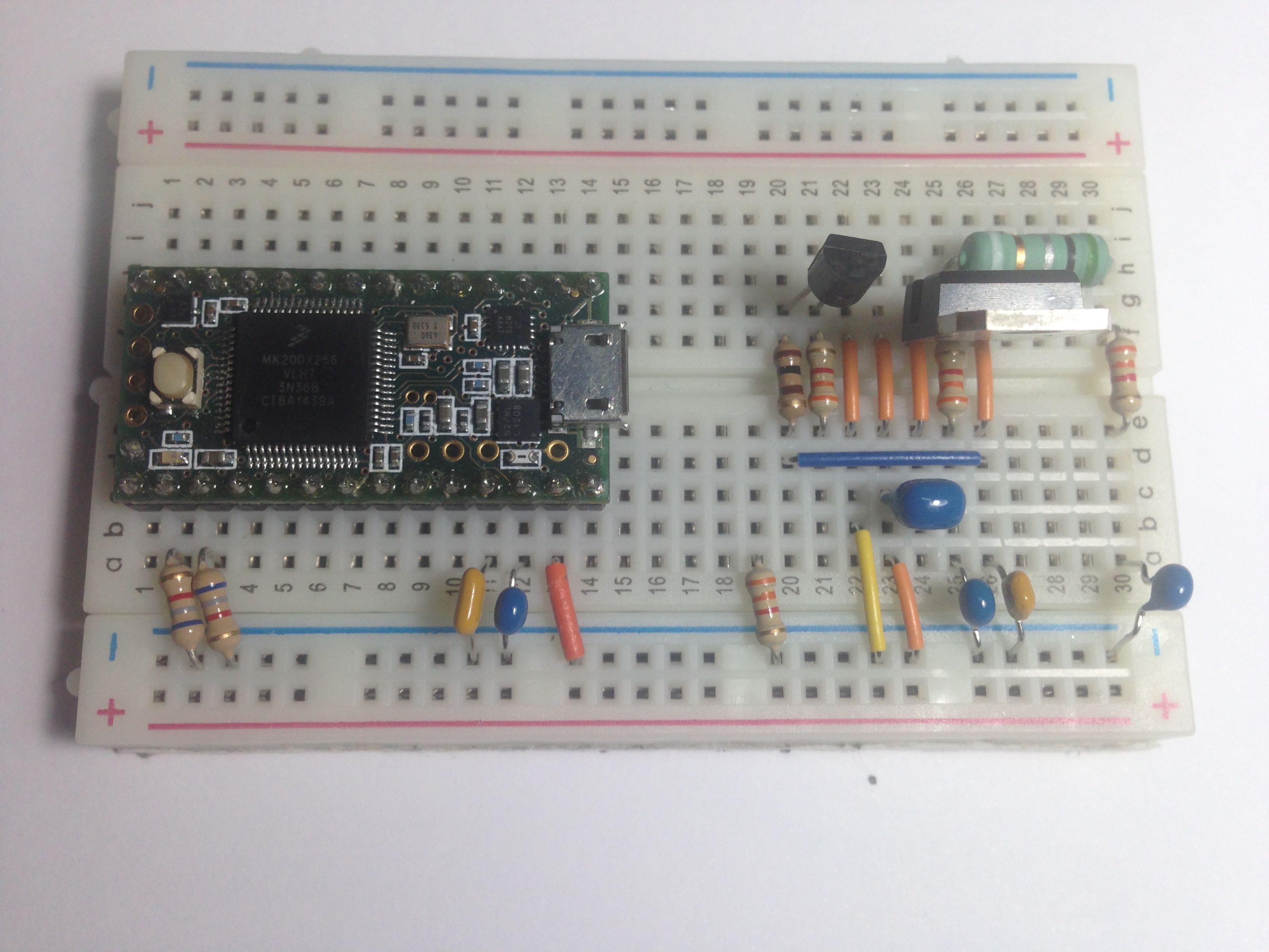
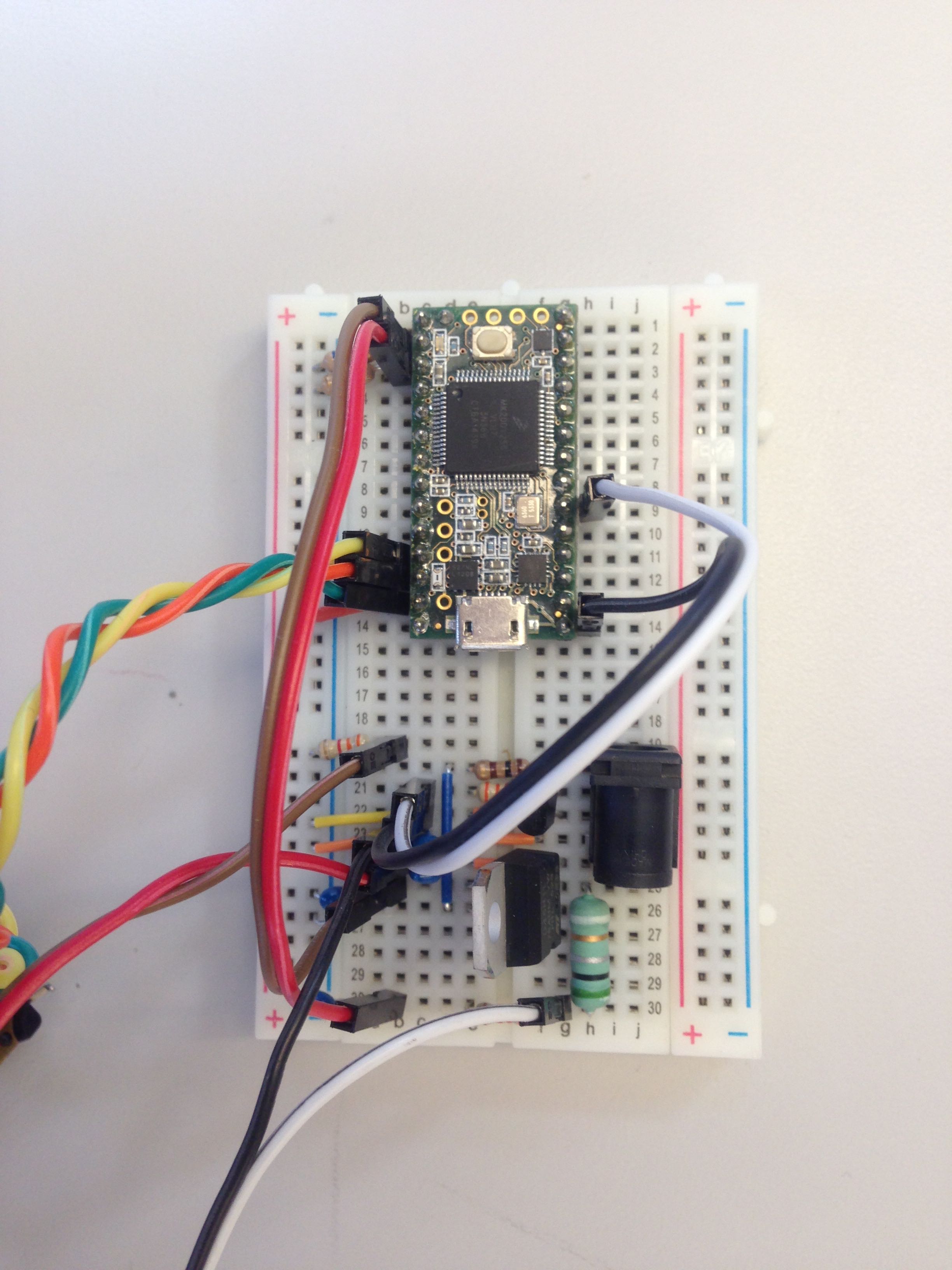
When Without any jumper wires, but in when in place and with additional components mounted the setup should look like the following (barrel jack has been removed for clarity for the moment):
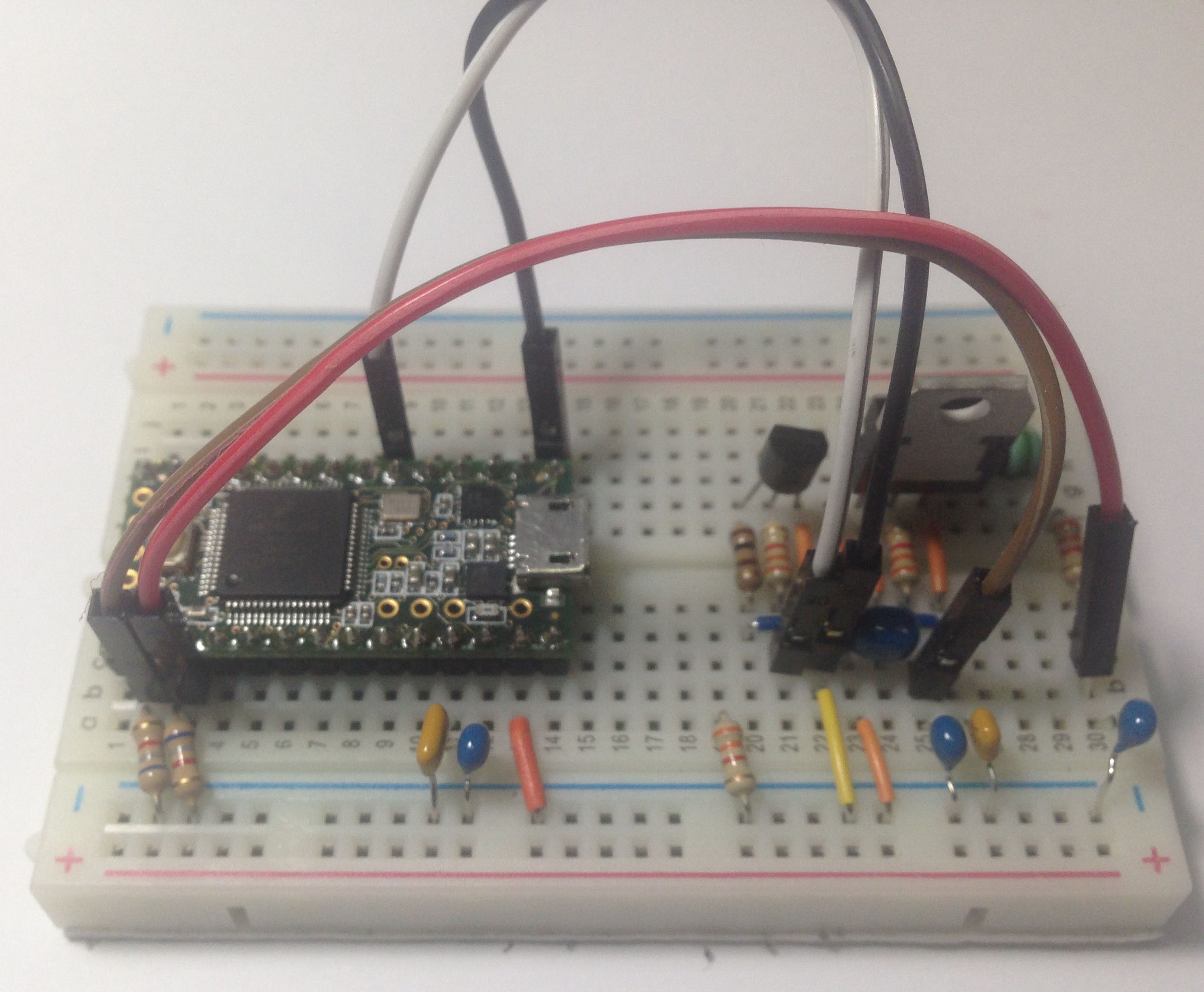
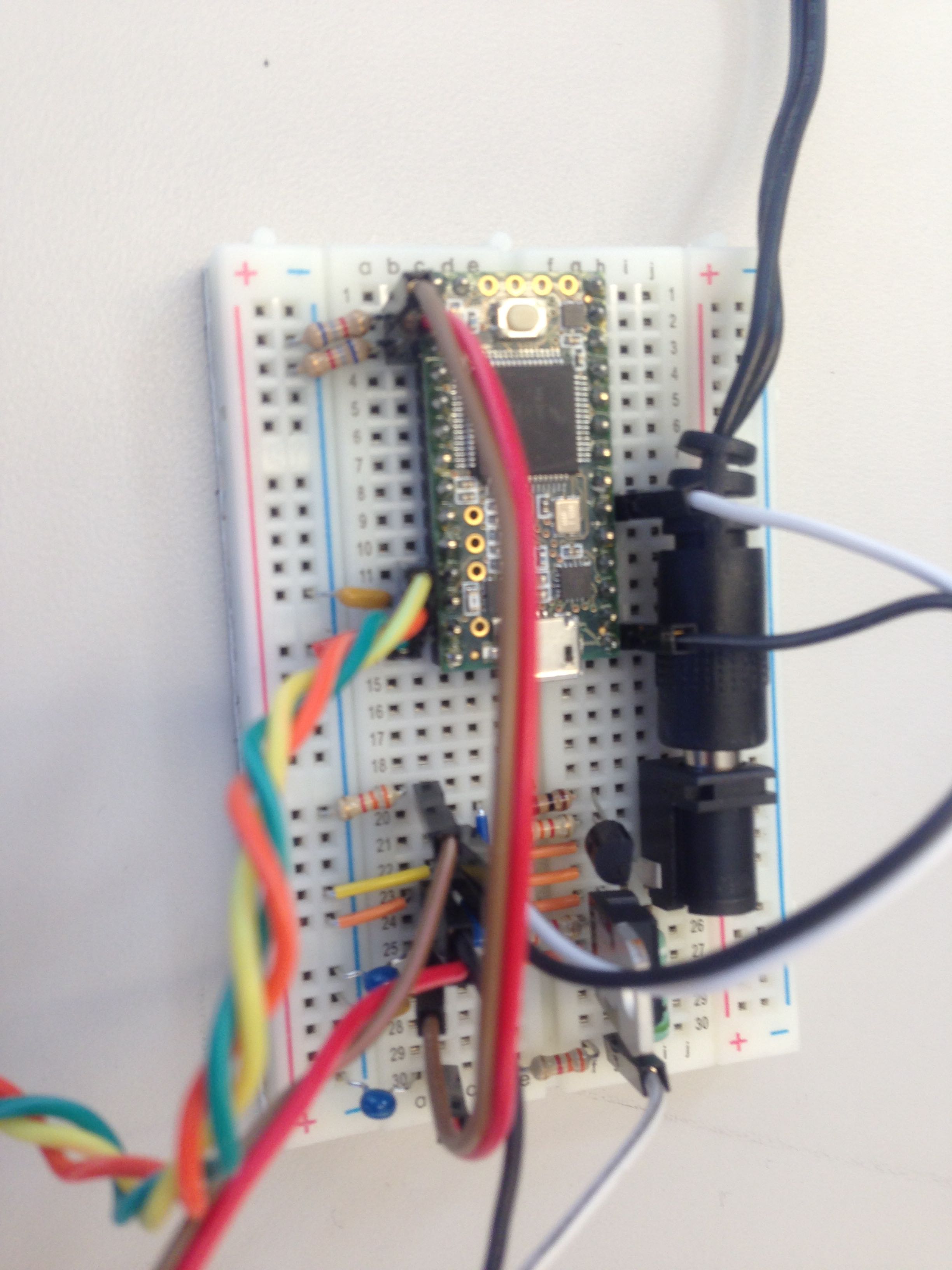
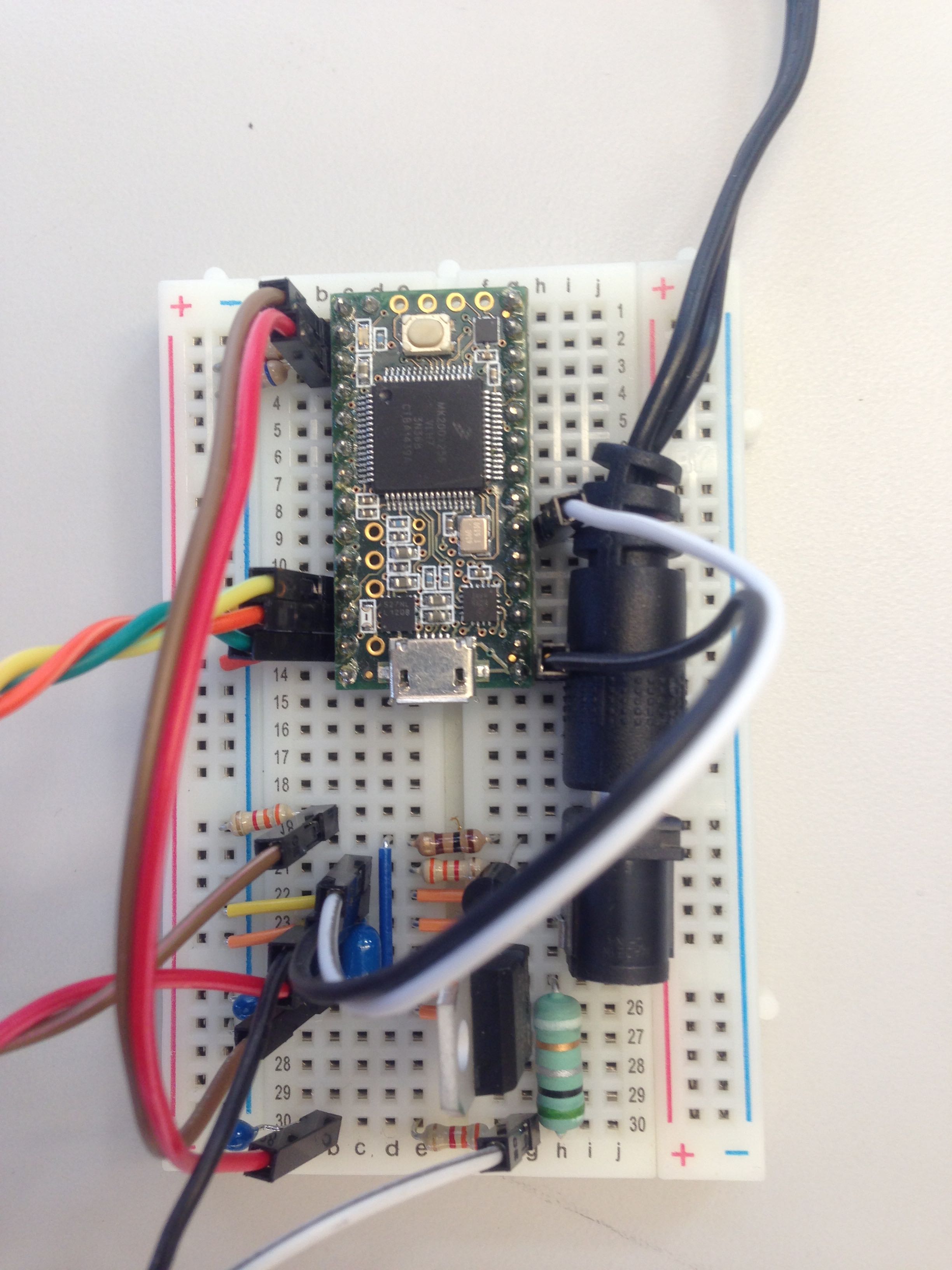
With all wire connections made between the Teensy and the rest of the breadboard-based circuit components we have the following:
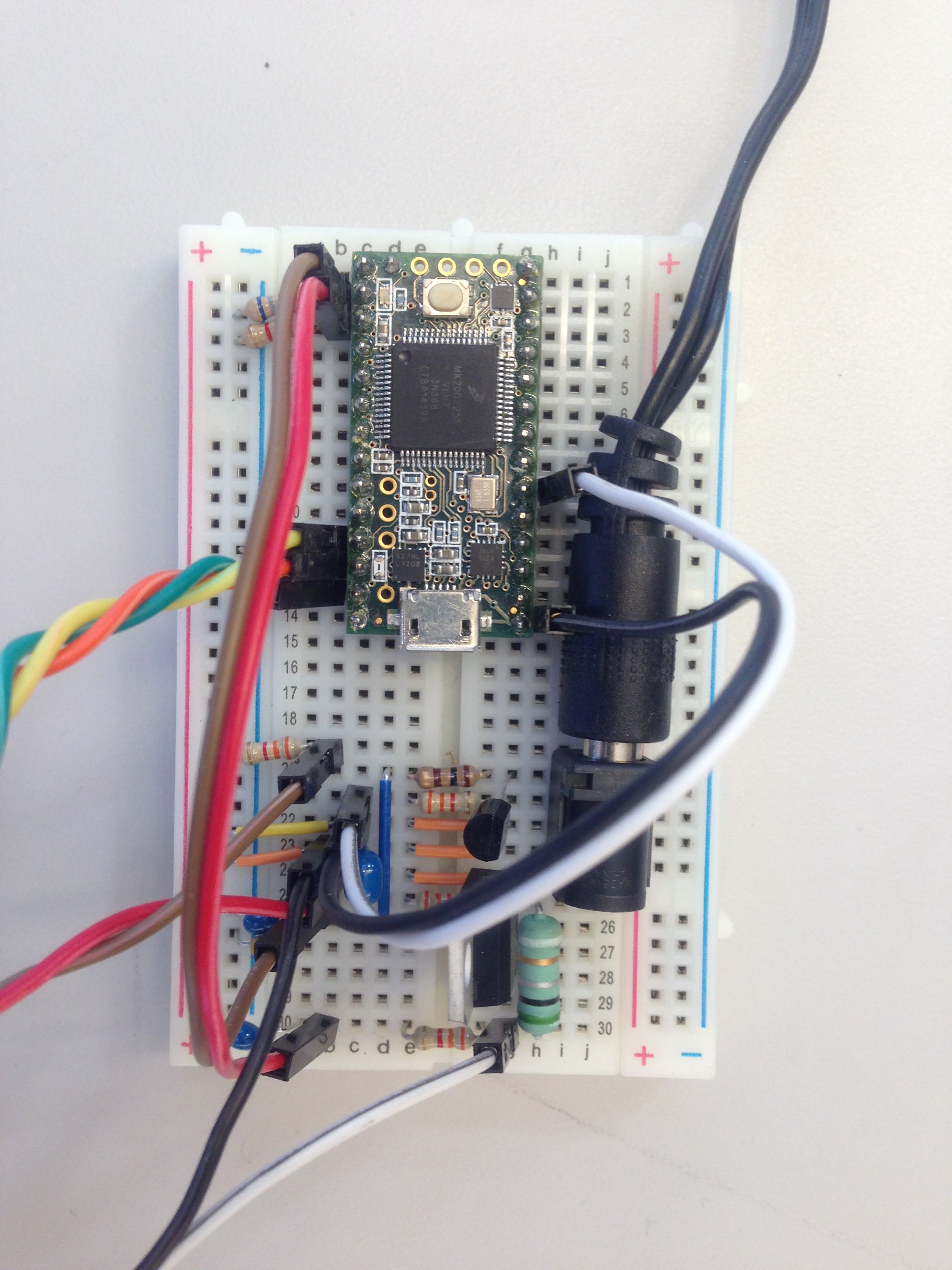
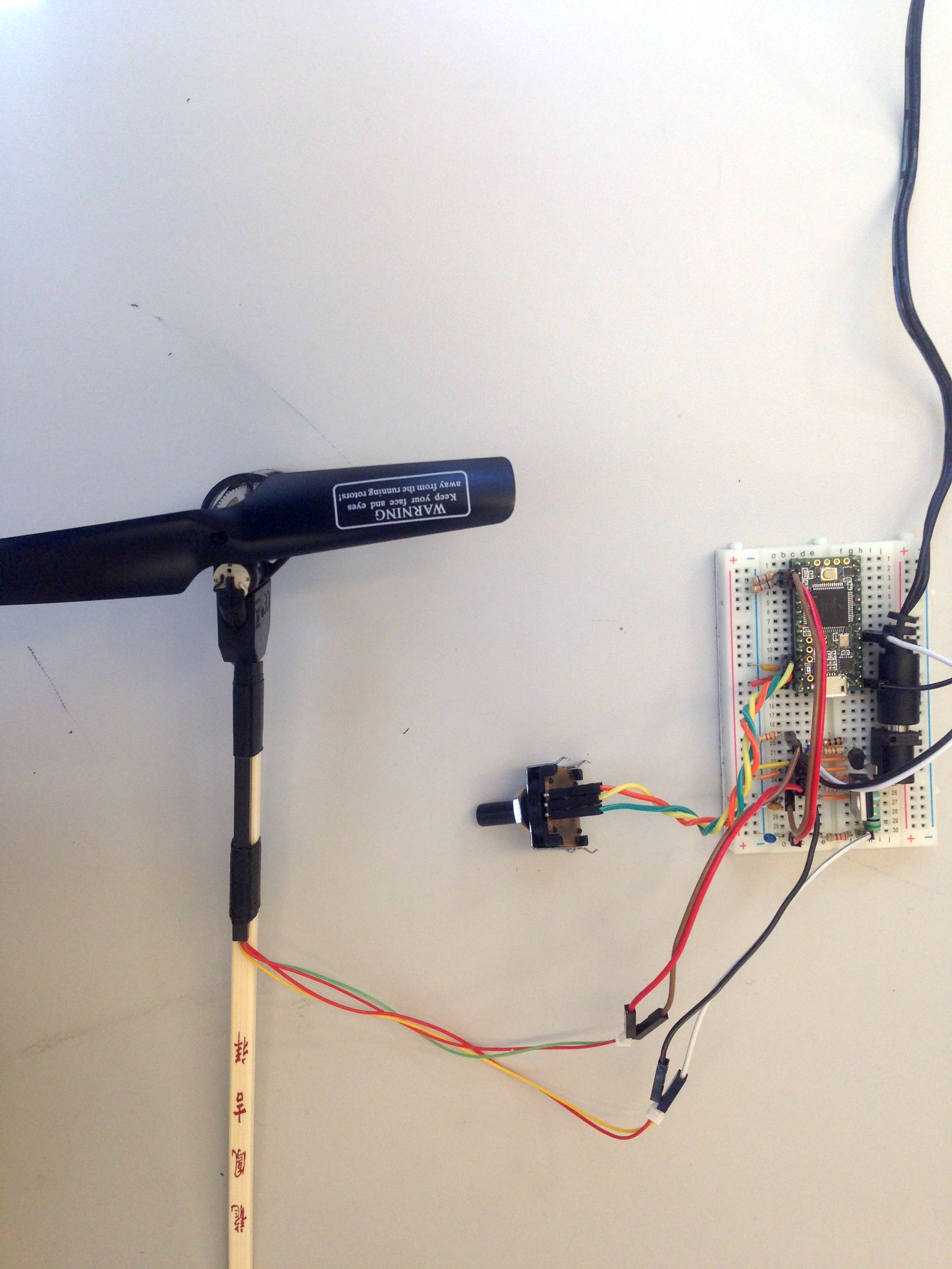
Then with all components (motor,LED, potentiometer integrated in) you should have a system which looks like the following:
This is a step by step assembly guide for the hardware of the course.
Please note: At times exact positions are used, however, below we describe how a breadboard is connected so you should be able to construct using any connected rows and columns that you like.
Below is the schematic for the completed circuit:
Please make sure that you have your the same components that we are listing below. Please note that if you are using an electrolytic capacitor that they are directional (they have a positive and negative terminal) so you will need to ground the negative terminal.
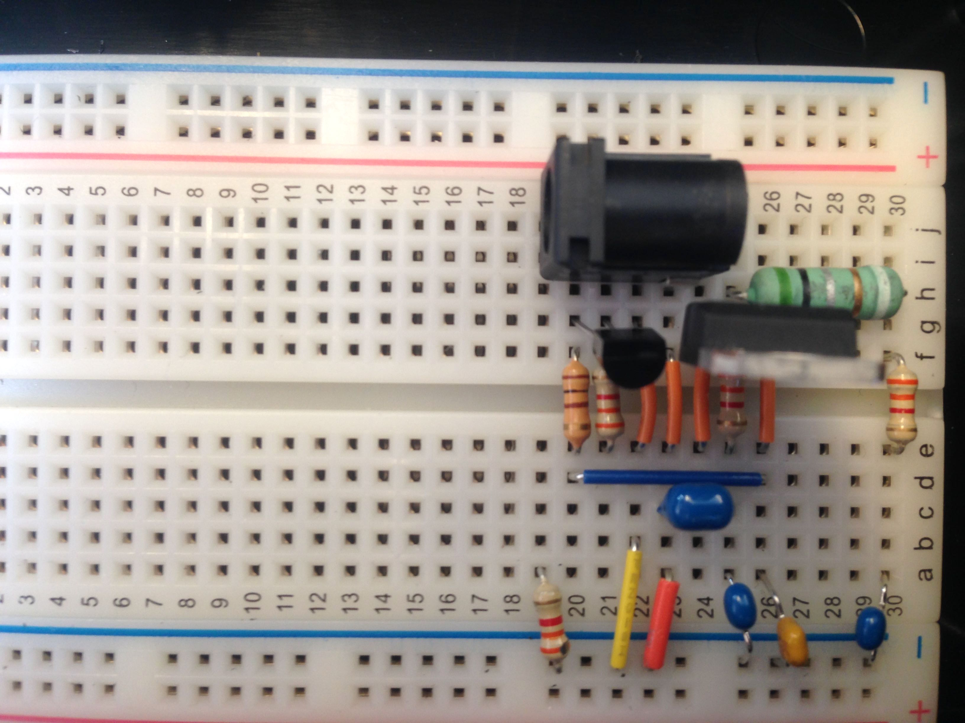
We will now connect the barrel jack to the breadboard.
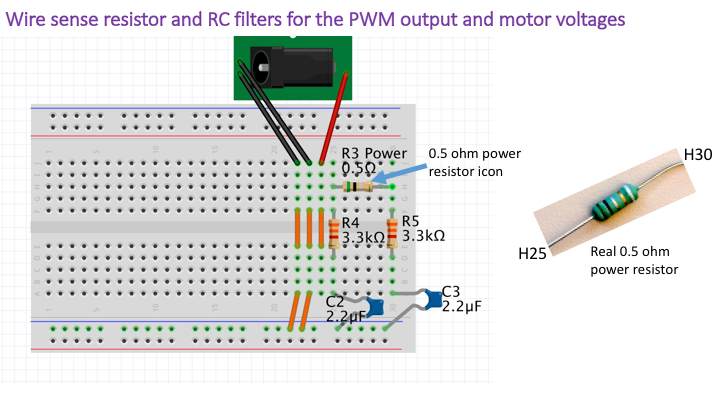
We wil now connect our power resistor with two RC filters to the breadboard.
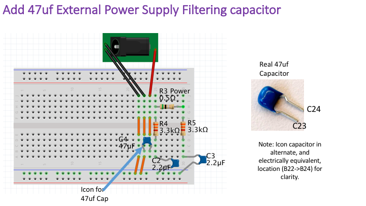
We now connect some filter capacitors to the breadboard. These capacitors try to remove any ripples in a DC signal to smooth it.
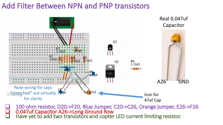
We will now install capacitors for the transistors.
We will now install our small NPN transistor. When the output from the micro-controller is high, this NPN transistor turns on a PNP power transistor, which that supplies current to the copter motor. The NPN transistor turns on the the PNP transistor by connecting its base resistor to ground.
We now install the power transistor. Please note the orientation of the power transistor, if you place the transistor in backwards, it may overheat and possibly damage the circuit. This transistor switches as much as two amperes of current, and can steer up to five watts of power to the propeller motor, so it should not surprise you that it can get hot even when wired correctly.
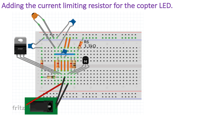
We are now adding a resistor for the copter LED if your quadcopter has an LED.
We then attach the quadcopter motor and LED to the breadboard.
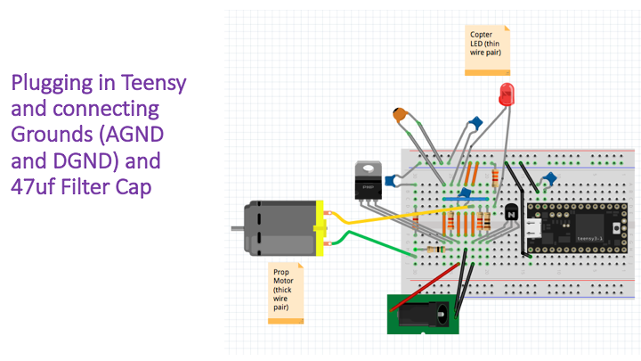
We will now insert the teensy into the circuit. Please note that with the teensy we both have to connect its ground to the breadboards ground and we must also place a capacitor between our ground pin and its neighbor.
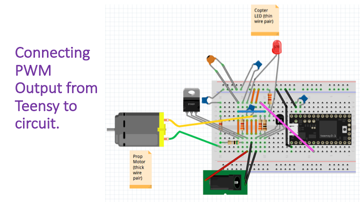
We now connect an output of the teensy as shown.
We will now connect the potentionmeter to the circuit. Note that the two end connections on the potentionmeter appear to be interchangable in the schematic, but physically, they are NOT. If you swap the ground and positive supply connections to the potentiometer, you will change the sign of the relationship between angle and voltage (the potentiometer is wired so that a rising arm produces increasing voltage and increasing angle, if you swap the ground and supply connections, then a rising arm will correspond to decreasing voltage).
Make sure to test your circuit now using lab 1. Remember that if you need any help debugging your circuit after you have attempted construction several times you can post a message on the discussion forum below with a picture and the staff will help you to debug your issue.